Continue to Site

Welcome to our site!

Electro Tech is an online community (with over 170,000 members) who enjoy talking about and building electronic circuits, projects and gadgets. To participate you need to register. Registration is free. Click here to register now.

  • Welcome to our site! Electro Tech is an online community (with over 170,000 members) who enjoy talking about and building electronic circuits, projects and gadgets. To participate you need to register. Registration is free. Click here to register now.

Pulse demodulation circuit -tunable frequencies - recommendations

Status
Not open for further replies.

fvnktion

New Member
A quick question before i get started:
1. Are there anything photo diode ic's packaged that can demodulate a 9 khz signal.

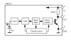
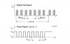
I need to be able to detect NIR pulses that are pulse modulated at 9 Khz. I have used NIR demodulation IC's such as the panasonic PNA4612 package that demodulates at 38 khz. What would be the best recommended method in building a circuit if i need to build one discretely to do detect a 9khz signal?

2. Is there a preferred method or circuit to detect pulses at a given frequency.
 
Edit: can alternately have a PV in photoconductive mode and it responds quicker. And if the 9 kHz is a CW tone, you can use a 567 to detect it.

You can get amplifier ICs with integral photo sensor, with a glass window. They are often in TO-5 can and sometimes in clear plastic. They can be expensive. The output is a voltage proportional to the illumination. If it's modulated light, you get an AC waveform superimposed on DC, or 50(60) Hz AC, which is the room ambient light. There is a maximum slew rate depending on what particalur device it is. the faster the slew rate, the lower the sensitivity or more expensive it is.

Or you can do your own, have a 'silicon photodiode in short-circuit mode' (look up those keywords) connected to an opamp. If you buy a PV that is very low capacitance, (and not very sensitive) you can have a fast opamp and recieve fast weak signals. If it's a higher capacitcance PV (that is sensitive), then don't waste money on fast opamps, cos these opamps won't make it much faster. To make it faster, lower the gain of the amplifier, which also reduces the sensitivity.
 
Last edited:
Great information marcbarcer - Thank you.

I am not sure what a 567 is in detecting the 9khz pulse train. Is it possible to frequency tune it to pick up on other frequencies? What type of device or circuit is this? Any other circuits that you might recommend for this application, (RC, PMA) ?

It sounds like you have a great deal of knowlegde in this area. Do you know of a good book or app notes that talk about this type of photo detection?


Thanks.
 
A 567 is meant for detecting a continuous tone. If the 9 kHz was an unmodulated continuous tone, it would be ideal. A 567 has a logic output which goes low if the tone is detected. Somehow I get the impression it's not a tone, but is a 9 kHz data rate pulse train, in which case a 567 wouldn't be any good anyway!

It's difficult to recommend anything, because there's little information you provided about the "9 kHz pulse train".
 
Somehow I get the impression it's not a tone, but is a 9 kHz data rate pulse train, in which case a 567 wouldn't be any good anyway!

Couldn't a digital pulse train such as the SIRC or other digital protocol be detected as easily as an analog sin wave at the same frequencies?


I need to be able to decode a modulated pulse train of digital signals in the NIR such as SIRC. When i say decode i need a to know when there is a signal being sent at my predefined frequency. I need to work in frequency ranges other than the typical 38 khz. I need to go as low 9khz.

Wouldn't the tone decoder or a PLL IC work for this?

Thanks
 
Last edited:
If the 'digital pulse train' is a continuous square wave signal, then a 567 could easily detect it. But then this 'digital pulse train' with no modulation wouldn't be carrying any information. If it did carry information, the 567 might lose lock. A 567 has a operation delay. You could maybe use one to demodulate, but there are better ways.

If it was something like the signal from an code encoder IC, the ideal decoder is the sister decoder IC.

If not the sister decoder IC, a microcontroller is usually the thing to decode a serial signal.

You're welcome to post information about the 9 kHz pulse train
 
Last edited:
Sorry for any confusion about the requirements. I am basically trying to recreate what is being done with a vishay tsop 4838 or panasonic pn4612 ir receivers. Figure1 shows their functional diagram. Figure 2 is the a 38khz modulated signal and its demodulated output.

I need to be able to change the modulation detection frequency from 38khz to a custom frequency such as 9khz.

If not the sister decoder IC, a microcontroller is usually the thing to decode a serial signal.

I will be using a microcontroller for a lot of other processing. I was hoping to find a hardware solution to this.

Thanks for all the great input.
 

Attachments

  • ir receiver functional diagram.jpg
    ir receiver functional diagram.jpg
    72.3 KB · Views: 1,252
  • mod - demod figure.jpg
    mod - demod figure.jpg
    85.5 KB · Views: 915
I suspect that the 38 kHz is preset inside the IC, no-changeable.

Is this the 'beam break' detector I saw on another posting?

If so, I think the only thing you need to is make sure the NIR you are transmitting is unique enough to be distinguisable by a receiver, while in the presence of interference, such as line frequency ambient light and remote controls. If it's only a beam break system, I think recreating IR remote control system might be making more work for yourself than you need.
 
I suspect that the 38 kHz is preset inside the IC, no-changeable.

This is exactly my problem. I need to recreate the demodulation that is being done by these IC's at different frequencies such as 9khz or as high as 500khz.

Is this the 'beam break' detector I saw on another posting?
I saw the post you are referring to and this has nothing to do with it. This has nothing to do with beam breaking.

Simply put i need to recreate the functionality of above stated devices (tsop 4838 or panasonic pn4612) at different frequecies. Anywhere from 9khz to 500khz.

From what i have been reading, it looks like my best bet is to use a PLL being fed a reference frequency(possibly PWM of micro) and then reading the VCO error voltage? I could use a comparator to interrupt a micro to tell me that there is a carrier frequency within range of my reference frequency. It appears that by using a PLL i would be able to detect different modulation schemes such as FSK, Manchester, Pulse position coding or Pulse width coding.

Based on the figure of modulated - demodulated waveform, do you think this would be a good method?
 
Last edited:
OK I think I know now what the original question is.

The idea is to recreate the functionality of tsop 4838 or panasonic pn4612, but at all frequencies from 9khz to 500khz.

I didn't understand what you mean about the idea a pll being fed a ref frequency and reading vco 'error voltage'. Nor the comparator either. So I can't comment on it.

Maybe this requires either a high speed ADC & FFT analysis, or some lateral thinking outside the box.
 
Status
Not open for further replies.

Latest threads

New Articles From Microcontroller Tips

Back
Top