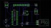
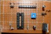
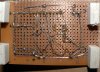
I'm using my own PCB I made for just the PIC, 7805, and LCD, with a 2K pot on the lcd contrast pin. I made the PCB layout based on your edit from this:
**broken link removed**
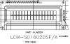
Same connections as this, only there is no reset button, no sensor line, and no memory button. I have a 10 pin header with all the wires of the LCD lined up in order as well(1-6,11-14), then a 2 pin header for LCD backlight for 15&16.
**broken link removed**
Same connections as this, only there is no reset button, no sensor line, and no memory button. I have a 10 pin header with all the wires of the LCD lined up in order as well(1-6,11-14), then a 2 pin header for LCD backlight for 15&16.
")