Hi!
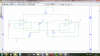
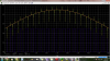
I have created spice schematics circuit of a sample and hold circuit consisting of 2opamps, n-channel MOSFET, and two voltage sources. The output doesnt resemble samplen hold. I have attatched the .png files of the circuit and simulation. Please help!
Thanks!
I have created spice schematics circuit of a sample and hold circuit consisting of 2opamps, n-channel MOSFET, and two voltage sources. The output doesnt resemble samplen hold. I have attatched the .png files of the circuit and simulation. Please help!
Thanks!