Continue to Site

Welcome to our site!

Electro Tech is an online community (with over 170,000 members) who enjoy talking about and building electronic circuits, projects and gadgets. To participate you need to register. Registration is free. Click here to register now.

  • Welcome to our site! Electro Tech is an online community (with over 170,000 members) who enjoy talking about and building electronic circuits, projects and gadgets. To participate you need to register. Registration is free. Click here to register now.

Problems with the LM317T regulator

Status
Not open for further replies.

nkukard

New Member
Hi guys,

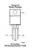
I built the LM317T example regulator here, page 7, bottom right.
https://www.electro-tech-online.com/custompdfs/2011/01/LM317T-ST.pdf

Cin - 100nf ceramic
D1/D2 - 1N4004
R1 - 240 ohm, 1/4 watt
R2 - 4k7 pot
Cadj - 10nf/50v
Co - 2200uf/50v

My input is switched clean 24v DC.

My problem is R1 gets damn hot when the pot is turned to closing on 0. Also, with a multimeter attached to the vout, I'm getting 23.5v +-, even when adjusting the pots very slowly.

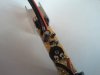
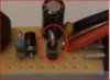
Here is a pic of my project, there is no track breaking.
**broken link removed**

I must be doing something wrong?
 
anyone got any ideas what could be wrong? my only alternative is to hook up the regulator + pot + resistor in the simplest config and try like that
 
You have a diode in backwards between Vin and Vout.

It should go between Vout and Adjust.

Pete.
 

Attachments

  • 317.JPG
    317.JPG
    39.4 KB · Views: 434
Last edited:
Oh ... the bottom left leg of the pot in the pic I took of me holding it is cut off above the board, just incase anyone thinks its connected :)
 
You should have a safety resistor in series with the pot, when you bring it down near 0, the current gets very high, that's why it's heating up.

Here is another ref circuit I used...
**broken link removed**

Is there a way to work out how much current is flowing through the resistor, because as far as my Multisim goes it says around 0.01A on an meter put between the resistor and Vout.
 
The multisim is fine; it is your wiring on the stripboard that is all screwed up. I make one end of R1 tied to Vin; not Vout.
 
The multisim is fine; it is your wiring on the stripboard that is all screwed up. I make one end of R1 tied to Vin; not Vout.

Pins as far as I read from left to right are Vadj, Vin, Vout .... R1 is tied between Vadj and Vout.

I'm posting another pic from the side where you can see where the pins are going more clearly.
 
Here is a pic from another angle to see where the legs are connected
 

Attachments

  • 2011-01-25 16.27.27.jpg
    2011-01-25 16.27.27.jpg
    1.5 MB · Views: 345
R1 has 1.25V across it. Then if it is 240 ohms (used with a more expensive LM117) then the current in R1 and R2 is 1.25V/240 ohms= 5.2mA.
If R1 is 120 ohms for an LM317 then the current is 10.4mA. The current is actually slightly higher because the current from the ADJ pin is 50uA to 100uA and is also in R2.

I agree that one of your diodes is connected backwards.
 
Pins as far as I read from left to right are Vadj, Vin, Vout .... R1 is tied between Vadj and Vout.

I'm posting another pic from the side where you can see where the pins are going more clearly.

Not on my LM317T:
 

Attachments

  • LM317T.png
    LM317T.png
    7.7 KB · Views: 601
Yes its your pins on the reg that is screwed up.

Input is on the outside and output is the centre leg.

Pete.
 
There's nothing wrong with the diagram. All you have to do is to replace R2 220R 0.25w resistor with a 0,5w 220R resistor. Just remember to add the 2200uF cap in parallel with C1 if you use a transformer
 
Last edited:
R1 must not be higher than 120 ohms for the less expensive LM317 or the output voltage will rise without a load.
R1 must not be higher than 240 ohms for the more expensive LM117.

Then the pot value must be changed.
 
There's nothing wrong with the diagram. All you have to do is to replace the 220R 0.25w resistor with a 0,5w 220R resistor.
There is no 220 ohm resistor, it is wrong at 240 ohms.
If R1 is 220 ohms then it dissipates only 0.007W so a tiny 0.1W resistor is fine and a big 1/2W resistor is not needed.
 
R1 must not be higher than 120 ohms for the less expensive LM317 or the output voltage will rise without a load.
R1 must not be higher than 240 ohms for the more expensive LM117.

Then the pot value must be changed.

Can you show me where you get 220 ohm from? I really want to learn as the datasheet gives a 240 ohm example, if you can show me where you get the values from and the calculation you use I'd really appreciate it. Or even refer me to more documentation to read.
 
As usual, Scrooge is a bit dogmatic. It doesn't matter much if R1 is anywhere from 100 to 240 Ohms. The resistor value stems from the minimum load current spec for the LM317, and to a lesser amount, that the current through R1 be large compared to the Adj pin current.

If you know a priori that the load current will always be much over the min. current specified for the LM317, then you can raise the impedance of the voltage divider. I have used as much as 1K for R1. At 1K, the regulation begins to suffer a bit, because the Adjust pin current starts approaching a larger fraction of the current through R1.
 
Last edited:
Status
Not open for further replies.

Latest threads

New Articles From Microcontroller Tips

Back
Top