Continue to Site

Welcome to our site!

Electro Tech is an online community (with over 170,000 members) who enjoy talking about and building electronic circuits, projects and gadgets. To participate you need to register. Registration is free. Click here to register now.

  • Welcome to our site! Electro Tech is an online community (with over 170,000 members) who enjoy talking about and building electronic circuits, projects and gadgets. To participate you need to register. Registration is free. Click here to register now.

Problem with Battery Balancing Circuit

Status
Not open for further replies.
Hi all I have designned a pcb to balance batteries, by using MOSFET's in there linear region (act like resistors). I have designned this circuit to balance 6 batteries the problem I am having at the moment is that, when I apply a voltage across one of the circuits (i.e. C1+ and C2+ of 5V),the other circuits are turning on and I am measuring 5V at the emitter and collector of each of the other optocouplers. However I have not turned on any of the optocouplers there is no voltage across the diodes of the optos. Can anyone please advice. Below are images of the circuits I developed, I have basically repeated the circuit below 6 times in series this image has two of them connected up with a simulation I created is also attached I made in LTSpice. Can anyone else explain why, the top circuit, there is a voltage at the emitter of the circuit, and also why the MOSFET is turning on when there is no voltage across the diode of the OPTO. Thanks Art
 

Attachments

  • IMG_8623.JPG
    IMG_8623.JPG
    1.2 MB · Views: 157
  • opto-fetactiveload3.asc
    4.5 KB · Views: 105
hi Arthur,
[ref your PM]
Could you explain a little more when saying 'a battery balancing circuit.?'
I guess you know the 4N25 has a poor transfer efficiency and low output current.

Eric

EDIT:
Are you trying to connect 6 off, 3.7v batteries in series.?
 
Hi,

Also, why would you apply a voltage to C1 and C2.
 
hi Arthur,
[ref your PM]
Could you explain a little more when saying 'a battery balancing circuit.?'
I guess you know the 4N25 has a poor transfer efficiency and low output current.

Eric

EDIT:
Are you trying to connect 6 off, 3.7v batteries in series.?
Hi,

Also, why would you apply a voltage to C1 and C2.

Hi have made an updated version of the simulation which should hopefully explain the circuit I have setup, I have built a PCB to test this and the test I am currently carrying out I have added in the simulation i.e. only turning on the opto of one of the circuits. The problem I am having is that the other circuits are then turning ON i.e. voltages measured at the emitter and also at the gates of the FETS when they shouldn't be ON because their optos haven't been turned on. Also sorry this was an older simulation it was meant to be 6 5V batteries. Please let me know if I have gone wrong anywhere or what can be improved so that it functions in the way intended would be greatly appreciated. Thanks Art
 

Attachments

  • opto-fetactiveload(5V).asc
    14.1 KB · Views: 101
hi A,

You have the 'vgate' label assigned to two points in your circuit, so what is on the lower active Vgate will appear on theUpper Vgate.!
E
 
hi A,

You have the 'vgate' label assigned to two points in your circuit, so what is on the lower active Vgate will appear on theUpper Vgate.!
E
Hi yeah just noticed that it was an older simulation, the most current one I have posted should have the setup I am considering
 
Hi,
Although you measure 5v across the opto transistor, the opto transistors are not conducting.
Also I measure no current flowing the main power FET.??
E
 
Alright damn, completley forgot to look at current, so just to double check, althought there is voltage measurement there is no current flowing from the Drain to the Source? I can't believe I forgot to check current
 
hi A,
This is what I see with just 3 batteries, the bottom opto is enabled.
Note I have changed the COMMON and Gnd Ref to suit my tests.

E
 

Attachments

  • A001.gif
    A001.gif
    46.1 KB · Views: 120
Hi,

If you still have a problem try disconnecting several of the opto outputs that way they can not turn anything on even if damaged.
 
No this is fine I made a mistake with my interpretation, there is a voltage present at the collector and emitter of the opto but there is no current flowing between both. Thanks Art
 
Here is one with a transistor not an op-amp. I am getting 2.4A.
upload_2017-2-24_19-4-3.png
 

Attachments

  • opto-fetactiveload-ron.asc
    4.1 KB · Views: 91
Here is one with a transistor not an op-amp. I am getting 2.4A.
View attachment 104551


Hi,

What is that transistor there doing for us, limiting the current to 100 amps? :)

I have a feeling that 2.4 amps is due to the transconductance of the mosfet only.
 
I don't know why I said 2.4A. Now I am getting 13A.
We don't know what current is needed. "3.7V" ??????

Back in 1980 something, I helped build a battery balancing circuit that went into trucks. 12v+12v It was PWM so little loss in heat. It does not take much current to balance a battery. You do not need to handle the full charging current.

If current>1A I would go PWM. My 2 battery circuit took current out of the battery with too much voltage and put current into the battery with too little voltage.

My circuit did not care what the battery voltage was, it only compared the voltages. V1=V2
 
Hi again Ron,

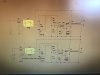
If you look at the sense resistor in that circuit is it only 0.005 ohms, so it would take about 100 amps through the mosfet to get that transistor to start to turn on. With 0.05 ohms, it would take about 10 amps. With the original circuit and same sense resistor values it would be about 10 amps and 1 amp respectively which unfortunately is still not right because the circuit will not function as balancer as is anyway.

It is actually a good thing you posted a different circuit because now i think that makes us take another look at what exactly the OP was trying to do in the first place, which if i understand this project right, does not look right at all.

In a battery balancing circuit, we have two main concerns:
1. The current through ALL the cells, which should be the same for all cells that are not too close to full charge yet, and with medium accuracy.
2. The voltage across EACH individual cell, which should be limited to 4.20 volts for a normal Li-ion cell for example and with good accuracy.

The usual way to get this is to provide a current limited power source (say 1 amp) that has enough voltage to reach the total series combination of all the cells that are to be charged in the same string, and to limit each cell's voltage on an individual basis by shunting any unwanted current around the cell (shunt regulator).
So for example if we connect four cells in series and provide at least 4.2*4=17.2v and current limited to 1 amp, then conenct a shunt regulator to each cell, as each cell gets near full charge the shunt regulator for each cell starts to bypass some of the current to that cell and keeps it from over charging.

As it is right now, all the mosfet does is limit the current through the mosfet itself, which is not what we want.

If we want to limit current on a cell by cell basis, that would be harder to do because we definitely need to limit voltage on a cell by cell basis. It is easier to limit the current to the whole series string, then limit only the voltage on a cell by cell basis.

This means that we need a single circuit that can limit current, then each shunt regulator needs to measure the voltage across it's respective cell and shunt current around the cell when the voltage starts to get near 4.2 volts.

The only difference between the shunt regulators and the normal single cell series regulator is that the shunt regulator draws more current as the cell voltage rises while the series regulator cuts back (lowers) the current as the cell voltage rises near to 4.20 volts.

BTW i like to charge my cells to 4.15v which supposedly allows them to age better.

So for 8 cells in one series string, we need one current limiter circuit and 8 shunt voltage regulators, and the shunt regulators need to have good accuracy. I would not try to obtain the reference from a forward biased diode but use a voltage reference diode or something like that.

I think modern day NiMH cell 15 minute fast chargers use PWM as they have to handle 10 amps charge current for each cell. That might get complicated for the OP here though. I think other slightly slower chargers might use PWM too these days.
 
Last edited:
Yes! MrAl, you can see the big picture.
I was having a hard time with a current source(s) across the battery charger.
BUT
I assumed a different function. Because each current source is individually controlled; Start out with all current sources off. Monitor each battery voltage. When one battery voltage gets too high, turn on its current source for 1 second, then off again. (repeat) This way the over charged battery(s) gets bypassed. When all of the batteries are at voltage stop charging. We don't know what is controlling the opto-isolators.

4.15V X 15A = too much power. (or maybe 10A) Then 5X when all but one battery is full.
About 50 watts X 5 = 250 watts of heat.
Next it is to work in a small box with out air flow. This is not going to work.

I could build 6 independent; 12V to 4.25V 10A isolated battery chargers. Power loss per battery will be 3 to 5 watts each. This should be about the same as a 24V 10A charger but the balancing creates no heat.
 
Hi,

Yeah i dont know what the opto's are doing here either, i guess we'll have to wait for the OP's reply.

Also, even with an Li-ion cell that is bypassed, at 4.2v and 1 amp current that's already 4.2 watts per cell when they are all fully charged, and even if we turn off then, we still see that just before the last cell is fully charged. That's a lot right there in modern times. By contrast, my home brewed version uses a buck switching regulator so regardless what the state of the cell is it is still rather high efficiency.
 
Status
Not open for further replies.

Latest threads

New Articles From Microcontroller Tips

Back
Top