Continue to Site

Welcome to our site!

Electro Tech is an online community (with over 170,000 members) who enjoy talking about and building electronic circuits, projects and gadgets. To participate you need to register. Registration is free. Click here to register now.

  • Welcome to our site! Electro Tech is an online community (with over 170,000 members) who enjoy talking about and building electronic circuits, projects and gadgets. To participate you need to register. Registration is free. Click here to register now.

Problem with actuator and relay

Status
Not open for further replies.

tom_the_chemist

New Member
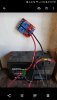
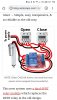
Trying to build an automatic chicken door using a linear actuator that runs on timers to close and open following a diagram I found online. Unfortunately, I have seemingly ruined more dpdt relays than I care to admit but I cannot figure out what is tripping them. The problem appears to occur when I hook the actuator up to the dpdt relay. Connecting all of the wires except the actuator, the relay performs as it should. I tested this and it shown in the video attached. Also, I connected a volt meter and confirmed that the relay was working. But once the actuator is connected and a load applied the relay fails almost instantly. One or both lights come on engaging the relays whenever power is applied. In the picture, you can see that only the positive and negative are attached to the relay but both relays are engaged.
 
Here is a pic of the relay after hooking the actuator to it. Notice the red lights are used to indicate that a relay is engaged.
 

Attachments

  • Screenshot_20190505-205904_Photos.jpg
    Screenshot_20190505-205904_Photos.jpg
    471.9 KB · Views: 198
Hey Tom,
do you have a schematic of the complete circuit you have running thus far?
Or links to the circuit you have used initially, along with any changes that you personally made to it/them?
Might the actuator be exceeding the current rating of the relays?
Do you have a link to the actuator you are using?
 
Here are the battery, actuator, and relay's I am using.
 

Attachments

  • Screenshot_20190505-212619_Amazon Shopping.jpg
    Screenshot_20190505-212619_Amazon Shopping.jpg
    275.9 KB · Views: 183
  • Screenshot_20190505-212550_Amazon Shopping.jpg
    Screenshot_20190505-212550_Amazon Shopping.jpg
    202.3 KB · Views: 186
  • Screenshot_20190505-212518_Amazon Shopping.jpg
    Screenshot_20190505-212518_Amazon Shopping.jpg
    261.2 KB · Views: 185
The write-up is very hard to understand.

Let's mention a couple of things.
The actuator needs to have limit switches.
The actuator might coast.
The relay would not be my choice. An automotive relay would be better.
I believe the ON time has to be greater than how long it takes to open/close the door respectively.

External limit switches are preferred. When limit switches are used, they have to be rated for the relay current. Automotive relay coild currents are fairly large. the contact ratings are like 40 A. You can buy two relays and a harness essentially configured for this application.
There is a suggested polarity because SOME have built in diodes. MOST schematics IGNORE this. there are a couple of different terminal arrangements as well. Even with limit switches, the system does not consume power when th\e door is either open or closed.

Simplisticly, one relay is OPEN and the other is CLOSE. If they are both on at the same time, the motor stops. The way the relays should be arranged, you will get an instantaneous stop but because there are nolimit switches, the actuator might coast.


Wiring is easy to describe and it;s mostly an automotive door lock type circuit. You can make the relay use a switched positive voltage to activate or a switched negative one.

The basic idea is to have the commons of the two relays connect to the motor and the NC contacts of both relays go to ground. In the unenergised state, the motor is shorted. Thinking a little far ahead. when the motor is commanded to stop via an external limit switch, the motor acts as a generator into a short. This can be a problem. When the actuator starts, you have a 2-5x surge in current. Again a problem. A 40 A rated relay really helps here.

OK, now what?. The NO contacts of each relay goes to +12, thus when one of the relays are activated and end sees +12 ad ground. When the other is activated, the polarity gets reversed.

When driving relays from a solid state device it;s customary to put a diode across the relay coil in the opposite direction that current would normally "flow". This absorbs the inductive spoke when the relay turns off. This spike can kill a solid state device.

if both relays are activated at the same time, the both sides of the motor see +12 so there is zero volts across the motor. The motor stops.

So, one timer activates the open relay for longer than it takes to open an similarly for the close relay,

Without external limit switches the actuator will coast.


I've attached a a .PDF (my design) that has a lot of options. It has the ability to interface OPEN, CLOSED and MOVING signals to whatever.

IMHO, a simple simple timer is a STUPID method unless I don;t know chickens. I do know they are color blind, but I don;t know thier bedtime and waking habits. I suspect it's based on daylight and not time. I would use an astronomic timer which you tell it the location and it computes sunrise and sunset. You can generally set the clock to use specific times or a relative time. At home. I turn on a lamp at 1/2 hour past sunset and off at 11:30. The timer is AC powered with battery backup.

The .PDF is very comprehensive.

Don;t know how your planning to keep the battery charged, but the alarm industry has pre-built supples with battery backup.
You might decide solar, but you still need the proper parts. Your battery should probably be of a "deep-cycle" type.

Here **broken link removed** is a dual relay socket basically pre-wired.

Now, you can likely use your relay gizmo to make the limit switch currents smaller, BUT there can be yet another problem called wetting current. Switches depending on how they are designed need a minimum switching current too which is used to "clean" the contacts.
 

Attachments

  • Motor-Limits.pdf
    31 KB · Views: 167
Last edited:
That is a very strong actuator and might damage any chickens that get trapped in it. You might want to consider mounting the actuator to pull a string to open the hatch and then let gravity close it.

Mike.
 
The write-up is very hard to understand.

Let's mention a couple of things.
The actuator needs to have limit switches.
The actuator might coast.
The relay would not be my choice. An automotive relay would be better.
I believe the ON time has to be greater than how long it takes to open/close the door respectively.

External limit switches are preferred. When limit switches are used, they have to be rated for the relay current. Automotive relay coild currents are fairly large. the contact ratings are like 40 A. You can buy two relays and a harness essentially configured for this application.
There is a suggested polarity because SOME have built in diodes. MOST schematics IGNORE this. there are a couple of different terminal arrangements as well. Even with limit switches, the system does not consume power when th\e door is either open or closed.

Simplisticly, one relay is OPEN and the other is CLOSE. If they are both on at the same time, the motor stops. The way the relays should be arranged, you will get an instantaneous stop but because there are nolimit switches, the actuator might coast.


Wiring is easy to describe and it;s mostly an automotive door lock type circuit. You can make the relay use a switched positive voltage to activate or a switched negative one.

The basic idea is to have the commons of the two relays connect to the motor and the NC contacts of both relays go to ground. In the unenergised state, the motor is shorted. Thinking a little far ahead. when the motor is commanded to stop via an external limit switch, the motor acts as a generator into a short. This can be a problem. When the actuator starts, you have a 2-5x surge in current. Again a problem. A 40 A rated.
.

Is it my write-up that is difficult to understand? If so, I can try to clarify any confusion.

Thanks for your detailed response. It is quite helpful. The actuator does have limit switches built-in.

Before moving to new designs, I would like to understand what is failing in the original design. Do you think it is the initial current surge? The relays are rated to 10 Amps. The actuator draws 4.7 amps. So maybe the 2x - 5x surge is exceeding the 10 amp rating for the relay?

Would this design, or the new design you share, benefit from flyback diodes?

I have looked at auto relays and that seems like the way to go. Thanks for linking.
 
That is a very strong actuator and might damage any chickens that get trapped in it. You might want to consider mounting the actuator to pull a string to open the hatch and then let gravity close it.

Mike.

Good point. Once I get the circuitry figured out, I will see what I can do to safeguard the chickens.
 
Sorry, I have one more question. I didnt see an amp rating for the relay linked by KeepItSimpleStupid, however many of the relays on that site are rated for 10 amps. Would these have the same issue as the relays that I have been using?
 
The screen shots help, but links are way better. Please post links to the actuator, timer, and relay pages.

You don't state what you are trying to achieve. I assume it is to move the actuator in one direction for a fixed amount of time, and then later move it in the other direction for a fixed amount of time. yes / no ?

If yes, then it is critical to determine if the actuator has limit switches built-in; many do, but not all. If not, then the switches *must* to be added to the door frame.

ak
 
Yes, the goal is for the door to open in the morning and then close in the evening.

Actuator

https://www.amazon.com/WINDYNATION-...52792&s=gateway&sprefix=12+inch+linear&sr=8-6

Timer

https://www.amazon.com/FAVOLCANO-CN...BS9PZX2GZWE&psc=1&refRID=ZKQXEMQNHBS9PZX2GZWE

Relay

https://www.amazon.com/SMAKN®-Chann...BS9PZX2GZWE&psc=1&refRID=ZKQXEMQNHBS9PZX2GZWE

Battery

https://www.amazon.com/ExpertPower-...7HTTSQ18BR5&psc=1&refRID=FZXF85JQA7HTTSQ18BR5

Also, I should state that the battery will be solar charged. That is setup and works great.

According to the page for the actuator, it has limit switches.
 
According to the page for the actuator, it has limit switches.
Then you can do this with one timer (that is programmable for at least two brief ON periods per day) and one DPDT impulse relay.

Or stick with what you've got. There is nothing wrong in the text description of the circuit.

ak
 
I only gave you a link to the dual socket. Here https://www.mouser.com/datasheet/2/418/NG_DS_V23134-X0000-A001_0314_134_0314-844400.pdf is a general datasheet for an automotive relay rated at 40 A. The terminals usually face down.
Note that 12 V relay has a 90 ohm coil, so I = 12/90 or about 130 mA.

Would this design, or the new design you share, benefit from flyback diodes?

Any design would. The timers are solid state, so the surges would be seen by the timers. Diodes can be soldered directly to the fast on terminals on the relay and still have room for the socket. A 1n4001 is fine. For automotive use, use a 200 PIV diode.
 
Update: I finally got my 40 amp spst Bosch style relays and they work quite well. The dpdt relays that I had been using were rated for around 10 amps. The initial amps at switching must have been too high for the dpdt causing it to fail.

However, my next hurdle is that I am not exactly sure how I can use the spst relays to switch polarity to run the actuator. I worked on this for several hours last night but every configuration that appeared to switch polarity would have likely shorted. I was trying to accomplish using two relays.

The box of relays I ordered contained five relays and i am wondering if a H-bridge using four of those would be the best option to accomplish my goal. In some of my research this appeared to potentially be one method for reversing polarity using spst relays.

If there are alternative options that would be better, I am open to looking at all those. However, just remember that I am a newbie and complex wiring diagrams are over my head. Thanks.
 
To reverse a motor requires a dpdt relay (google). Two spst relays could be used to mimick one but you may get shoot through currents.

Mike.
 
However, my next hurdle is that I am not exactly sure how I can use the spst relays to switch polarity to run the actuator. I worked on this for several hours last night but every configuration that appeared to switch polarity would have likely shorted. I was trying to accomplish using two relays.

Back in my post #8. Edited.


ring is easy to describe and it;s mostly an automotive door lock type circuit. You can make the relay use a switched positive voltage to activate or a switched negative one.

The basic idea is to have the commons of the two relays connect to the motor and the NC (Normally Closed) contacts of both relays go to ground. In the unenergised state, the motor is shorted. Thinking a little far ahead. when the motor is commanded to stop via, the motor acts as a generator into a short.

OK, now what?. The NO (Normally Open) contacts of each relay goes to +12, thus when one of the relays are activated and end sees +12 ad ground. When the other is activated, the polarity gets reversed.

If BOTH relays are activated, each side of the motor "sees" 12V, there is zero volts across the motor. The motor stops. So, both coils on or both off results in a stop/brake action.

Explained in another way. One terminal of the motor (A) can see ground or +12. The other side (B) can too. If +12 enters through A and exits at B, the motor rotates one way. If +12 enters at B and exits to ground at A, it goes the other. If A and B are both grounded, the motor stops. IF A and B both have +12, the motor stops.
 
Status
Not open for further replies.

Latest threads

New Articles From Microcontroller Tips

Back
Top