hkBattousai
Member
I've been trying to interface 18F2550 and a 128x64 pixel graphic LCD for weeks. I tried several libraries found on the web, but none of them made the LCD print a single pixel on the screen. I'm really stuck at the moment, and I need guidance and new ideas.
The best library I found so far is the one I found in this forum. You can access the thread from here. For simplicity, I'm going to add source source code of the library below.
I also checked the signal levels at both PIC and LCD pinouts by an oscilloscope, there are meaningful pulses, the system PIC is working for sure.
The major parts I used are listed below:
These are photos of my LCD:
**broken link removed**, **broken link removed**
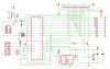
And these are photos of my circuit:
**broken link removed**, **broken link removed**
Code:
glcd.h
glcd.c
main.c
Do you have any suggestions to make this project work? If you need any other details about my system, please feel free to ask.
Any help or guidance will be appreciated greatly.
The best library I found so far is the one I found in this forum. You can access the thread from here. For simplicity, I'm going to add source source code of the library below.
I also checked the signal levels at both PIC and LCD pinouts by an oscilloscope, there are meaningful pulses, the system PIC is working for sure.
The major parts I used are listed below:
- IDE: MATLAB 8.40 Academic
- Compiler: Microchip C18 3.34 Academic
- LCD: WG12864B, with KS0108 Controller (Detailed datasheet, Electrical specifications)
- PIC: PIC18F2550, with 20MHz crystal(Page, Datasheet)
These are photos of my LCD:
**broken link removed**, **broken link removed**
And these are photos of my circuit:
**broken link removed**, **broken link removed**
Code:
glcd.h
Code:
#include <p18f2550.h>

#define GLCD_Data   PORTB
#define b_GLCD_GCS1 LATCbits.LATC7
#define b_GLCD_GCS2 LATCbits.LATC6
#define b_GLCD_RS   LATCbits.LATC0
#define b_GLCD_RW   LATCbits.LATC1
#define b_GLCD_E    LATAbits.LATA5
#define b_GLCD_On   LATCbits.LATC2
#define b_GLCD_BL   LATAbits.LATA4	// Not used in my project

#define TRIS_Data    TRISB
#define b_TRIS_GCS1  TRISCbits.TRISC7 //GCS1
#define b_TRIS_GCS2  TRISCbits.TRISC6 //GCS2
#define b_TRIS_RS    TRISCbits.TRISC0 //RS
#define b_TRIS_RW    TRISCbits.TRISC1 //RW
#define b_TRIS_E     TRISAbits.TRISA5 //E
#define b_TRIS_On    TRISCbits.TRISC2 //RST
#define b_TRIS_BL    TRISAbits.TRISA4 //backlight

void Delay(void);
unsigned char GLCD_Read(void);
void Wait_Not_Busy(void);
void GLCD_Write_Cmd(unsigned char data);
void GLCD_Write_Data (unsigned char data);
void ClearScreen(void);
void Init_GLCD(void);
void PutChar(unsigned char data);
unsigned char GLCD_Read_Data(void);
void SetPos(unsigned char x,unsigned char y);
void WritePosition(void);
void plot(unsigned char x,unsigned char y);
void hline(unsigned char x,unsigned char y1,unsigned char y2);
void vline(unsigned char x1,unsigned char x2,unsigned char y);
void box(unsigned char x1,unsigned char y1,unsigned char x2,unsigned char y2);
void PutMessage(static char rom *Message);
void PutLogo(static char rom *logo);
glcd.c
Code:
#include <p18f2550.h>
#include "glcd.h"

const rom unsigned char Font[96][7];
unsigned char i,XPos,YPos,W;

void plot(unsigned char x,unsigned char y){
unsigned char d;
	if(x>63){
		b_GLCD_GCS1=0;
		b_GLCD_GCS2=1;
		x-=64;
	}
	else
	{
		b_GLCD_GCS1=1;
		b_GLCD_GCS2=0;
	}
	GLCD_Write_Cmd(0x40+x);			//write column address
	GLCD_Write_Cmd(0xb8+(y>>3));	//write row address
	d=GLCD_Read_Data();				//dummy read
	d=GLCD_Read_Data();
	GLCD_Write_Cmd(0x40+x);			//write column address again
	d=d&(0xff-(1<<(y&7)));
	GLCD_Write_Data(d);
}

void hline(unsigned char x,unsigned char y1,unsigned char y2){
	for(i=y1;i<y2;i++)
		plot(x,i);
}

void vline(unsigned char x1,unsigned char x2,unsigned char y){
	for(i=x1;i<x2;i++)
		plot(i,y);
}

void box(unsigned char x1,unsigned char y1,
	unsigned char x2,unsigned char y2){
	vline(x1,x2,y1);
	vline(x1,x2,y2);
	hline(x1,y1,y2);
	hline(x2,y1,y2);
}

void Delay(void){
	_asm	NOP	_endasm
	_asm	NOP	_endasm
	_asm	NOP	_endasm
	_asm	NOP	_endasm
	_asm	NOP	_endasm
	_asm	NOP	_endasm
	_asm	NOP	_endasm
	_asm	NOP	_endasm
	_asm	NOP	_endasm
	_asm	NOP	_endasm
}

unsigned char GLCD_Read(void){
	b_GLCD_E=1;Delay();
	Delay();
	W=GLCD_Data;Delay();
	b_GLCD_E=0;Delay();
	return W;
}

void Wait_Not_Busy(void){
	TRIS_Data=0xff;
	b_GLCD_RS=0;
	b_GLCD_RW=1;
	if (b_GLCD_GCS1==1 && b_GLCD_GCS2==1){
		b_GLCD_GCS1=0;
		while (GLCD_Read()&0x80);
		b_GLCD_GCS1=1;
		b_GLCD_GCS2=0;
		while (GLCD_Read()&0x80);
		b_GLCD_GCS2=1;
	}
	else{
		while (GLCD_Read()&0x80);
	}
	TRIS_Data=0x00;
}

void GLCD_Write_Cmd(unsigned char data){
	Wait_Not_Busy();Delay();
	GLCD_Data = data;Delay();
	b_GLCD_RS=0;Delay();
	b_GLCD_RW=0;Delay();
	b_GLCD_E=1;Delay();
	Delay();
	b_GLCD_E=0;Delay();
}

void GLCD_Write_Data (unsigned char data){
	Wait_Not_Busy();Delay();
	GLCD_Data = data;Delay();
	b_GLCD_RS=1;Delay();
	b_GLCD_RW=0;Delay();
	b_GLCD_E=1;Delay();
	Delay();Delay();
	b_GLCD_E=0;Delay();
}

void MoveRight(void){
	if(++XPos==64){
		WritePosition();
	}
	if(XPos==128){
		XPos=0;
		YPos+=8;
		YPos=YPos&0x3f;
		WritePosition();
	}
}

void WritePosition(void){
	if(XPos>63){
		b_GLCD_GCS1=0;
		b_GLCD_GCS2=1;
	}
	else{
		b_GLCD_GCS1=1;
		b_GLCD_GCS2=0;
	}
	GLCD_Write_Cmd(0x40+(XPos&0x3f));	//column=0
	GLCD_Write_Cmd(0xb8+((YPos&0x3f)>>3));	//row=0
}

unsigned char GLCD_Read_Data(void){
	Wait_Not_Busy();
	TRIS_Data=0xff;
	b_GLCD_RS=1;
	b_GLCD_RW=1;
	b_GLCD_E=1;
	Delay();
	W=GLCD_Data;
	b_GLCD_E=0;
	TRIS_Data=0x00;
	return W;
}

void ClearScreen(void){
unsigned char i,j;
	b_GLCD_GCS1=1;Delay();
	b_GLCD_GCS2=1;Delay();
	for(i=0;i<8;i++)
	{
		GLCD_Write_Cmd(0x40);Delay();	//y=0
		GLCD_Write_Cmd(0xb8+i);Delay();	//x=0
		for(j=0;j<0x40;j++)
		{
			GLCD_Write_Data(0xff);Delay();
		}
	}
	SetPos(0,0);Delay();
}

void Init_GLCD(void){
unsigned char i;

    b_TRIS_GCS1=0;Delay();
    b_TRIS_GCS2=0;Delay();
    b_TRIS_RS=0;Delay();
    b_TRIS_RW=0;Delay();
    b_TRIS_E=0;Delay();
    b_TRIS_On=0;Delay();
    b_TRIS_BL=0;Delay();

    b_GLCD_On=1;Delay();
	b_GLCD_GCS1=1;Delay();
	b_GLCD_GCS2=1;Delay();
    b_GLCD_BL=1;Delay();
	GLCD_Write_Cmd(0x3f);Delay();	//display on
	GLCD_Write_Cmd(0xc0);Delay();	//z=0
	ClearScreen();Delay();
}

void PutChar(unsigned char data){
unsigned char i,d;
	if(data<32){
		switch(data){
			case 13:
				XPos=0;
			case 10:
				XPos=0;
				YPos+=8;
				YPos=YPos&63;
		}
		WritePosition();
	}
	else{
		for(i=0;i<7;i++){
			d=Font[data-32][i];
			if(d!=0x55){
				GLCD_Write_Data(d);
				MoveRight();
			}
		}
		GLCD_Write_Data(0xff);
		MoveRight();
	}
}

void PutMessage(static char rom *Message){
	while(*Message!=0)
		if(*Message==0x16){
			*Message++;
			XPos=*Message++;
			YPos=*Message++;
			WritePosition();
		}
		else
			PutChar(*Message++);
}

void PutLogo(static char rom *logo){
unsigned char w,h,bitcount,Byte;
	w=*logo++;
	h=*logo++;
	bitcount=0;
	do{
		for(i=0;i<w;i++){
			if(bitcount==0){
				bitcount=8;
				Byte=*logo++;
			}
			if(Byte&1) plot(XPos,YPos);
			XPos++;
			Byte/=2;
			bitcount--;
		}
		YPos++;
		XPos-=w;
	}while(--h);
}

void SetPos(unsigned char x,unsigned char y){
	XPos=x;
	YPos=y;
	WritePosition();
}

const rom unsigned char Font[96][7]={
	0xFF,0xFF,0xFF,0x55,0x55,0x55,0x55,	//	32
	0xFF,0xA0,0xFF,0x55,0x55,0x55,0x55,	//	33	!
	0xF8,0xFF,0xF8,0x55,0x55,0x55,0x55,	//	34	""
	0xEB,0x80,0xEB,0x80,0xEB,0x55,0x55,	//	35	#
	0xD9,0xB6,0x80,0xB6,0xCD,0x55,0x55,	//	36	$
	0x9C,0xEC,0xF7,0x9B,0x9C,0x55,0x55,	//	37	%
	0xC9,0xB6,0xFF,0xDD,0xAF,0x55,0x55,	//	38	&
	0xFB,0xFC,0xFF,0x55,0x55,0x55,0x55,	//	39	'
	0xE3,0xDD,0xBE,0x55,0x55,0x55,0x55,	//	40	(
	0xBE,0xDD,0xE3,0x55,0x55,0x55,0x55,	//	41	)
	0xEB,0xD5,0xE3,0xD5,0xEB,0x55,0x55,	//	42	*
	0xF7,0xF7,0xC1,0xF7,0xF7,0x55,0x55,	//	43	+
	0x7F,0x9F,0x55,0x55,0x55,0x55,0x55,	//	44	,
	0xF7,0xF7,0xF7,0xF7,0xF7,0x55,0x55,	//	45	-
	0xBF,0x55,0x55,0x55,0x55,0x55,0x55,	//	46	.
	0x9F,0xEF,0xF7,0xFB,0xFC,0x55,0x55,	//	47	/
	0xC1,0xAE,0xB6,0xBA,0xC1,0x55,0x55,	//	48	0
	0xFF,0xBD,0x80,0xBF,0xFF,0x55,0x55,	//	49	1
	0x9D,0xAE,0xB6,0xB6,0xB9,0x55,0x55,	//	50	2
	0xDD,0xBE,0xB6,0xB6,0xC9,0x55,0x55,	//	51	3
	0xE7,0xEB,0xED,0x80,0xEF,0x55,0x55,	//	52	4
	0xD8,0xB6,0xB6,0xB6,0xCE,0x55,0x55,	//	53	5
	0xC3,0xB5,0xB6,0xB6,0xCF,0x55,0x55,	//	54	6
	0xFE,0x8E,0xF6,0xFA,0xFC,0x55,0x55,	//	55	7
	0xC9,0xB6,0xB6,0xB6,0xC9,0x55,0x55,	//	56	8
	0xF9,0xB6,0xB6,0xD6,0xE1,0x55,0x55,	//	57	9
	0xEB,0x55,0x55,0x55,0x55,0x55,0x55,	//	58	:
	0x7F,0x97,0x55,0x55,0x55,0x55,0x55,	//	59	;
	0xF7,0xEB,0xDD,0xBE,0x55,0x55,0x55,	//	60	<
	0xEB,0xEB,0xEB,0xEB,0x55,0x55,0x55,	//	61	=
	0xBE,0xDD,0xEB,0xF7,0x55,0x55,0x55,	//	62	>
	0xFD,0xFE,0xAE,0xF6,0xF9,0x55,0x55,	//	63	?
	0xC1,0xBE,0xA2,0xFF,0xB1,0x55,0x55,	//	64	@
	0x83,0xED,0xEE,0xED,0x83,0x55,0x55,	//	65	A
	0x80,0xB6,0xB6,0xB6,0xC9,0x55,0x55,	//	66	B
	0xC1,0xBE,0xBE,0xBE,0xDD,0x55,0x55,	//	67	C
	0x80,0xBE,0xBE,0xDD,0xE3,0x55,0x55,	//	68	D
	0x80,0xB6,0xB6,0xB6,0xBE,0x55,0x55,	//	69	E
	0x80,0xF6,0xF6,0xF6,0xFE,0x55,0x55,	//	70	F
	0xC1,0xBE,0xB6,0xD6,0x8D,0x55,0x55,	//	71	G
	0x80,0xF7,0xF7,0xF7,0x80,0x55,0x55,	//	72	H
	0xBE,0x80,0xBE,0x55,0x55,0x55,0x55,	//	73	I
	0xDF,0xBF,0xBE,0xC0,0xFE,0x55,0x55,	//	74	J
	0x80,0xF7,0xEB,0xDD,0xBE,0x55,0x55,	//	75	K
	0x80,0xBF,0xBF,0xBF,0x55,0x55,0x55,	//	76	L
	0x80,0xFD,0xF3,0xFD,0x80,0x55,0x55,	//	77	M
	0x80,0xF9,0xF7,0xCF,0x80,0x55,0x55,	//	78	N
	0xC1,0xBE,0xBE,0xBE,0xC1,0x55,0x55,	//	79	O
	0x80,0xF6,0xF6,0xF6,0xF9,0x55,0x55,	//	80	P
	0xC1,0xBE,0xAE,0xDE,0xA1,0x55,0x55,	//	81	Q
	0x80,0xF6,0xE6,0xD6,0xB9,0x55,0x55,	//	82	R
	0xD9,0xB6,0xB6,0xB6,0xCD,0x55,0x55,	//	83	S
	0xFE,0xFE,0x80,0xFE,0xFE,0x55,0x55,	//	84	T
	0xC0,0xBF,0xBF,0xBF,0xC0,0x55,0x55,	//	85	U
	0xF0,0xCF,0xBF,0xCF,0xF0,0x55,0x55,	//	86	V
	0xF0,0xCF,0xBF,0xC7,0xBF,0xCF,0xF0,	//	87	W
	0x9C,0xEB,0xF7,0xEB,0x9C,0x55,0x55,	//	88	X
	0xF8,0xF7,0x8F,0xF7,0xF8,0x55,0x55,	//	89	Y
	0x9E,0xAE,0xB6,0xBA,0xBC,0x55,0x55,	//	90	Z
	0x80,0xBE,0xBE,0x55,0x55,0x55,0x55,	//	91	[
	0xFC,0xFB,0xF7,0xEF,0x9F,0x55,0x55,	//	92
	0xBE,0xBE,0x80,0x55,0x55,0x55,0x55,	//	93	]
	0xF7,0xFB,0xFD,0xFB,0xF7,0x55,0x55,	//	94	^
	0xBF,0xBF,0xBF,0xBF,0xBF,0x55,0x55,	//	95	_
	0xFC,0xFB,0xFF,0x55,0x55,0x55,0x55,	//	96	`
	0xDF,0xAB,0xAB,0x87,0x55,0x55,0x55,	//	97	a
	0x80,0xD7,0xBB,0xBB,0xC7,0x55,0x55,	//	98	b
	0xC7,0xBB,0xBB,0xD7,0x55,0x55,0x55,	//	99	c
	0xC7,0xBB,0xBB,0xD7,0x80,0x55,0x55,	//	100	d
	0xC7,0xAB,0xAB,0xB7,0x55,0x55,0x55,	//	101	e
	0xF7,0x81,0xF6,0xFD,0x55,0x55,0x55,	//	102	f
	0x67,0x5B,0x5B,0xA7,0x55,0x55,0x55,	//	103	g
	0x80,0xF7,0xFB,0xFB,0x87,0x55,0x55,	//	104	h
	0xC2,0xBF,0x55,0x55,0x55,0x55,0x55,	//	105	i
	0x7F,0x7B,0x82,0x55,0x55,0x55,0x55,	//	106	j
	0x80,0xEF,0xD7,0xBB,0x55,0x55,0x55,	//	107	k
	0xFE,0x80,0xFF,0x55,0x55,0x55,0x55,	//	108	l
	0x83,0xF7,0xFB,0x87,0xFB,0x87,0x55,	//	109	m
	0x83,0xF7,0xFB,0xFB,0x87,0x55,0x55,	//	110	n
	0xC7,0xBB,0xBB,0xC7,0x55,0x55,0x55,	//	111	o
	0x03,0xE7,0xDB,0xDB,0xE7,0x55,0x55,	//	112	p
	0xE7,0xDB,0xDB,0xE7,0x03,0x55,0x55,	//	113	q
	0x83,0xF7,0xFB,0xFB,0xF7,0x55,0x55,	//	114	r
	0xB7,0xAB,0xAB,0xDB,0x55,0x55,0x55,	//	115	s
	0xFB,0xC1,0xBB,0x55,0x55,0x55,0x55,	//	116	t
	0xC3,0xBF,0xBF,0xDF,0x83,0x55,0x55,	//	117	u
	0xE3,0xDF,0xBF,0xDF,0xE3,0x55,0x55,	//	118	v
	0xC3,0xBF,0xCF,0xBF,0xC3,0x55,0x55,	//	119	w
	0xBB,0xD7,0xEF,0xD7,0xBB,0x55,0x55,	//	120	x
	0xE3,0x5F,0x5F,0x83,0x55,0x55,0x55,	//	121	y
	0x9B,0xAB,0xAB,0xB3,0x55,0x55,0x55,	//	122	z
	0xF7,0xC9,0xBE,0x55,0x55,0x55,0x55,	//	123	{
	0xFF,0x80,0xFF,0x55,0x55,0x55,0x55,	//	124	|
	0xBE,0xC9,0xF7,0x55,0x55,0x55,0x55,	//	125	}
	0xFF,0xFF,0x55,0x55,0x55,0x55,0x55,	//	126	~
	0x01,0x7D,0x7D,0x7D,0x01,0x55,0x55,	//	127
};
main.c
Code:
#include <p18f2550.h>
#include "glcd.h"
#pragma config WDT		= OFF
#pragma config MCLRE		= ON
#pragma config DEBUG		= OFF
#pragma config LVP		= OFF
#pragma config PLLDIV		= 5			// need 5 for 20MHz xtal
#pragma config CPUDIV		= OSC1_PLL2	// CPU Clock = 96 MHz/2 = 48 MHz
#pragma config USBDIV		= 2			// 96MHz PLL/2 = 48 MHz for USB clock
#pragma config FOSC		= HSPLL_HS	// High Speed Crystal / Resonator with PLL enabled

void main (void)
{
	Init_GLCD();

	PutMessage((rom char*)"\x16\x24\x08 Blueroom\x16\x20\x10 Electronics\n Title:\n Author:\n Date:\n Hardware:");
	PutMessage((rom char*)"\x16\x38\x18Graphic demo.");
	PutMessage((rom char*)"\x16\x38\x20Mike Webb.");
	PutMessage((rom char*)"\x16\x38\x28June 20 2007.");
	PutMessage((rom char*)"\x16\x38\x30Unicorn.");
	box(1,1,126,62);

	while (1);

	// Working "Hello World" example
	/*unsigned char i, j;
	TRISB = 0;
	while (1)
	{
		PORTB = 0x00;
		Delay1KTCYx(i);
		PORTB = 0xFF;
		Delay1KTCYx(255-i);
	}*/
}
Do you have any suggestions to make this project work? If you need any other details about my system, please feel free to ask.
Any help or guidance will be appreciated greatly.
")
