Continue to Site

Welcome to our site!

Electro Tech is an online community (with over 170,000 members) who enjoy talking about and building electronic circuits, projects and gadgets. To participate you need to register. Registration is free. Click here to register now.

  • Welcome to our site! Electro Tech is an online community (with over 170,000 members) who enjoy talking about and building electronic circuits, projects and gadgets. To participate you need to register. Registration is free. Click here to register now.

Problem interfaceing PIC18F2550 and KS0108 LCD

Status
Not open for further replies.
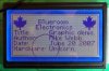
ok. my lcd is atm12864D - datasheet is on the web, but there are mystakes-informations in the table and in description are different. For data I use portB, for others portD (CS1-RD3; CS2-RD2; D/I-RD7; RW-RD6; E-RD5; RESET-RD4) - I use PIC18F4525. I connected leds like you (by the way good work ;) ) and the program doesn't get trouhg init part. I write code for led to init part and it fall down in ClearScreen.

void ClearScreen(void){
unsigned char m,n;
b_GLCD_GCS1=1;Delay();
b_GLCD_GCS2=1;Delay();
Delay10KTCYx(0);
Delay10KTCYx(0);
blinkLed(3);
Delay10KTCYx(0);
Delay10KTCYx(0);
for(m=0;m<8;m++){
GLCD_Write_Cmd(0x40);Delay(); //y=0
GLCD_Write_Cmd(0xb8+m);Delay(); //x=0
for(n=0;n<0x40;n++){
GLCD_Write_Data(0x00);Delay();
}
}
it works to for cycle and than it doesn't work. if I measure it, data=0; RS=0;RW=1;CS1=1;CS2=0 - this I don't understand, before blinkled CS1=CS2=1.
 
I couldn't understand your problem. But check this out, I rewrote the entire library, renamed the function names, etc, and added a configuration file to it! Download the file in my attachment (Rename the "zip" file extension to "rar", I don't believe that they don't support "rar" extension...).


Configuration file (glcd_config.h):
Code:
// EN: Enable
// DI: Data/Instruction
// CS: Chip Select
// RS: Reset
// RW: Read/Write


#ifndef _GLCD_CONFIG_H_
#define _GLCD_CONFIG_H_


// EN bit is complemented on the LCD side
//#define GLCD_CFG_EN_COMPLEMENTED

// DI bit is complemented on the LCD side
// By default, D is active high and I is active low
// Uncomment this line if your LCD has different pinout configuration
//#define GLCD_CFG_DI_COMPLEMENTED

// CSx bits are complemented on the LCD side
//#define GLCD_CFG_CS_COMPLEMENTED

// RS bit is complemented on the LCD side
#define GLCD_CFG_RS_COMPLEMENTED

// RW bit is complemented on the LCD side
// By default, R is active high and W is active low
// Uncomment this line if your LCD has different pinout configuration
//#define GLCD_CFG_RW_COMPLEMENTED


// EN bit
#ifdef  GLCD_CFG_EN_COMPLEMENTED
#define GLCD_EN_HIGH 0
#define GLCD_EN_LOW  1
#else
#define GLCD_EN_HIGH 1
#define GLCD_EN_LOW  0
#endif

// DI bit
#ifdef  GLCD_CFG_DI_COMPLEMENTED
#define GLCD_DI_HIGH 0
#define GLCD_DI_LOW  1
#else
#define GLCD_DI_HIGH 1
#define GLCD_DI_LOW  0
#endif

// CSx bits
#ifdef  GLCD_CFG_CS_COMPLEMENTED
#define GLCD_CS_HIGH 0
#define GLCD_CS_LOW  1
#else
#define GLCD_CS_HIGH 1
#define GLCD_CS_LOW  0
#endif

// RS bit
#ifdef  GLCD_CFG_RS_COMPLEMENTED
#define GLCD_RS_HIGH 0
#define GLCD_RS_LOW  1
#else
#define GLCD_RS_HIGH 1
#define GLCD_RS_LOW  0
#endif

// RW bit
#ifdef  GLCD_CFG_RW_COMPLEMENTED
#define GLCD_RW_HIGH 0
#define GLCD_RW_LOW  1
#else
#define GLCD_RW_HIGH 1
#define GLCD_RW_LOW  0
#endif


#endif	// #ifndef _GLCD_CONFIG_H_

DI is the RS in the old library, not to confuse with Reset.

Just uncomment the GLCD_CFG_xx_COMPLEMENTED constant if your LCD has that pin complemented. For example in my LCD only the Reset pin is complemented, so I only activated GLCD_CFG_RS_COMPLEMENTED constant. Using this configuration file, this library can be used to drive any 128x64 pixel LCD!! Now this library is device-independent!
 

Attachments

  • glcd_c18_library.zip
    2.8 KB · Views: 282
My problem is that my program does't get trought init routine. It fall down at part clearscreen when it do this: GLCD_Write_Cmd(0x40) it go to wait_not_busy and there is fall down. i measured lcd and the values I write before. I don't know how to repair it.
 
My problem is that my program does't get trought init routine. It fall down at part clearscreen when it do this: GLCD_Write_Cmd(0x40) it go to wait_not_busy and there is fall down. i measured lcd and the values I write before. I don't know how to repair it.

What do you mean by "to fall down"?
Does your code enter an infinite loop inside ClearScreen() function, or your LCD stop responding after ClearScreen?
 
I connect leds to parts of init (in wait_not_busy; write_cmd and clearscreen)
and when program do clearscreen, part :GLCD_Write_Cmd(0x40) it go to wait_not_busy and there the program stop and I don't know why. maybe it do infity loop in
if (b_GLCD_GCS1==1 && b_GLCD_GCS2==1){
b_GLCD_GCS1=0;
while (GLCD_Read()&0x80);
b_GLCD_GCS1=1;
b_GLCD_GCS2=0;
while (GLCD_Read()&0x80);
b_GLCD_GCS2=1;
}
else{
while (GLCD_Read()&0x80);
}
 
I try something and I found part where is the problem. This is it:

unsigned char GLCD_Read(void){
b_GLCD_E=1;Delay();
Delay();
Wa=GLCD_Data;Delay();
blinkLed(3);
b_GLCD_E=0;Delay();
return Wa;
}

two times it go trought right but when it go third it ends in blinkLed(3); and led blink and blink and blink. Any ideas?

Obviously, it gets stuck at "while (GLCD_Read()&0x80);" line. GLCD_Read() never returns something maskable with 0x80 value.

1) Check all your wiring. Use a multimeter and test if you have any disconnection in your circuit wires.
2) Make sure that your display is compatible with this library. Some bits in the LCD may be complemented, while they are not in the library. If that's the case, use the modified library I attached above to configure those pins.
3) Place some blinkLed() functions inside GLCD_Read() function to find out the exact line where it reads the wrong value. Though this step would not make any contribution to solve your problem, it may help you learn the mechanism of the LCD controller.

EDIT: And wrap your code between "code" "/code" tags.
 
Last edited:
Still nothing. I built it again, measure it but everything is ok.
program do still the same. it do display on and when it do set adres z (start line) it do again GLCD_Read. i havent any ideas.

#include <p18f4525.h>
#include "glcd.h"

const rom unsigned char Font[96][7];
unsigned char i,XPos,YPos,Wa;
void blikLed(unsigned char led);
void plot(unsigned char x,unsigned char y){
unsigned char d;
if(x>63){
b_GLCD_GCS1=0;
b_GLCD_GCS2=1;
x-=64;
}
else
{
b_GLCD_GCS1=1;
b_GLCD_GCS2=0;
}
GLCD_Write_Cmd(0x40+x); //write column address
GLCD_Write_Cmd(0xb8+(y>>3)); //write row address
d=GLCD_Read_Data(); //dummy read
d=GLCD_Read_Data();
GLCD_Write_Cmd(0x40+x); //write column address again
d=d&(0xff-(1<<(y&7)));
GLCD_Write_Data(d);
}

void hline(unsigned char x,unsigned char y1,unsigned char y2){
for(i=y1;i<y2;i++)
plot(x,i);
}

void vline(unsigned char x1,unsigned char x2,unsigned char y){
for(i=x1;i<x2;i++)
plot(i,y);
}

void box(unsigned char x1,unsigned char y1,
unsigned char x2,unsigned char y2){
vline(x1,x2,y1);
vline(x1,x2,y2);
hline(x1,y1,y2);
hline(x2,y1,y2);
}

void Delay(void){
_asm NOP _endasm
_asm NOP _endasm
_asm NOP _endasm
_asm NOP _endasm
_asm NOP _endasm
_asm NOP _endasm
_asm NOP _endasm
_asm NOP _endasm
_asm NOP _endasm
_asm NOP _endasm
}

void Wait_Not_Busy(void){
TRIS_Data=0xff;
b_GLCD_RS=0;
b_GLCD_RW=1;
if (b_GLCD_GCS1==1 && b_GLCD_GCS2==1){
b_GLCD_GCS1=0;
while (GLCD_Read()&0x80);
b_GLCD_GCS1=1;
b_GLCD_GCS2=0;
while (GLCD_Read()&0x80);
b_GLCD_GCS2=1;
}
else{
while (GLCD_Read()&0x80);
}
TRIS_Data=0x00;
}

unsigned char GLCD_Read(void){
blikLed(3);
Delay10KTCYx(0);
Delay10KTCYx(0);
Delay10KTCYx(0);
b_GLCD_E=1;
Delay();
Wa=GLCD_Data;
b_GLCD_E=0;Delay();
return Wa;
}

void GLCD_Write_Cmd(unsigned char data){
Wait_Not_Busy();
GLCD_Data=data;
b_GLCD_RS=0;
b_GLCD_RW=0;
b_GLCD_E=1;
Delay();
Delay();
b_GLCD_E=0;Delay();
}

void GLCD_Write_Data (unsigned char data){
Wait_Not_Busy();
GLCD_Data=data;
b_GLCD_RS=1;
b_GLCD_RW=0;
b_GLCD_E=1;Delay();
Delay();Delay();
b_GLCD_E=0;
}

void MoveRight(void){
if(++XPos==64){
WritePosition();
}
if(XPos==128){
XPos=0;
YPos+=8;
YPos=YPos&0x3f;
WritePosition();
}
}

void WritePosition(void){
if(XPos>63){
b_GLCD_GCS1=0;
b_GLCD_GCS2=1;
}
else{
b_GLCD_GCS1=1;
b_GLCD_GCS2=0;
}
GLCD_Write_Cmd(0x40+(XPos&0x3f)); //column=0
GLCD_Write_Cmd(0xb8+((YPos&0x3f)>>3)); //row=0
}

unsigned char GLCD_Read_Data(void){
Wait_Not_Busy();
TRIS_Data=0xff;
b_GLCD_RS=1;
b_GLCD_RW=1;
b_GLCD_E=1;
Delay();
Wa=GLCD_Data;
b_GLCD_E=0;
TRIS_Data=0x00;
return Wa;
}

void ClearScreen(void){
unsigned char m,n;
b_GLCD_GCS1=1;
b_GLCD_GCS2=1;
for(m=0;m<0x08;m++){
GLCD_Write_Cmd(0x40);Delay(); //y=0
GLCD_Write_Cmd(0xb8+m);Delay(); //x=0
for(n=0;n<0x40;n++){
GLCD_Write_Data(0x00);Delay();
}
}

SetPos(0,0);Delay();
}

void Init_GLCD(void){

b_TRIS_GCS1=0;
b_TRIS_GCS2=0;
b_TRIS_RS=0;
b_TRIS_RW=0;
b_TRIS_E=0;
b_TRIS_On=0;

b_GLCD_On=1;
b_GLCD_GCS1=1;
b_GLCD_GCS2=1;
GLCD_Write_Cmd(0x3f); //display on
blikLed(1);
GLCD_Write_Cmd(0xc0); //z=0
blikLed(2);
ClearScreen();
}

void PutChar(unsigned char data){
unsigned char i,d;
if(data<32){
switch(data){
case 13:
XPos=0;
case 10:
XPos=0;
YPos+=8;
YPos=YPos&63;
}
WritePosition();
}
else{
for(i=0;i<7;i++){
d=Font[data-32];
if(d!=0x55){
GLCD_Write_Data(d);
MoveRight();
}
}
GLCD_Write_Data(0xff);
MoveRight();
}
}

void PutMessage(static char rom *Message){
while(*Message!=0)
if(*Message==0x16){
*Message++;
XPos=*Message++;
YPos=*Message++;
WritePosition();
}
else
PutChar(*Message++);
}

void PutLogo(static char rom *logo){
unsigned char w,h,bitcount,Byte;
w=*logo++;
h=*logo++;
bitcount=0;
do{
for(i=0;i<w;i++){
if(bitcount==0){
bitcount=8;
Byte=*logo++;
}
if(Byte&1) plot(XPos,YPos);
XPos++;
Byte/=2;
bitcount--;
}
YPos++;
XPos-=w;
}while(--h);
}

void SetPos(unsigned char x,unsigned char y){
XPos=x;
YPos=y;
WritePosition();
}

void blikLed(unsigned char led)
{
int j; for (j=0; j<2; j++)
{
switch (led)
{
case 0:
LATAbits.LATA0 = 1;
Delay10KTCYx(0);
LATAbits.LATA0 = 0;
Delay10KTCYx(0);
break;
case 1:
LATAbits.LATA1 = 1;
Delay10KTCYx(0);
LATAbits.LATA1 = 0;
Delay10KTCYx(0);
break;
case 2:
LATAbits.LATA2 = 1;
Delay10KTCYx(0);
LATAbits.LATA2 = 0;
Delay10KTCYx(0);
break;
case 3:
LATAbits.LATA3 = 1;
Delay10KTCYx(0);
LATAbits.LATA3 = 0;
Delay10KTCYx(0);
break;
case 4:
LATAbits.LATA4 = 1;
Delay10KTCYx(0);
LATAbits.LATA4 = 0;
Delay10KTCYx(0);
break;
default:
LATAbits.LATA0 = 0;
LATAbits.LATA1 = 0;
LATAbits.LATA2 = 0;
LATAbits.LATA3 = 0;
LATAbits.LATA4 = 0;
break;
}
}
}
 
I've just written two new functions using my basic analytical geometry knowledge:

Code:
void glcd_DrawLine(unsigned char x1, unsigned char y1, unsigned char x2, unsigned char y2)
{
	// y = ((y2 - y1) / (x2 - x1)) * (x - x1) + y1
	float m = (float) (y2 - y1) / (float) (x2 - x1);
	for(glcdI=x1; glcdI<=x2; glcdI++) glcd_Plot(glcdI, (unsigned char) (m * (glcdI - x1) + y1));	
}

void glcd_DrawCircle(unsigned char x, unsigned char y, unsigned char r)
{
	// y = y0 - sqrt(r^2 - (x0 - x)^2)
	// y = y0 + sqrt(r^2 - (x0 - x)^2)
	unsigned char rt;	// The root term
	signed char i, j;
	for (i=x-r; i<=x+r; i++)
	{
		rt = (signed char) sqrt((float) r*r - (float) (x-i)*(x-i));
		if ((i < 0) || (i > 127)) continue;
		j = y - rt;
		if (!((j > 63) || (j < 0))) glcd_Plot((unsigned char) i, (unsigned char) j);
		j = y + rt;
		if (!((j > 63) || (j < 0))) glcd_Plot((unsigned char) i, (unsigned char) j);
	}
}

glcd_DrawLine() is working good, but glcd_DrawCircle doesn't display anything. Do you guys have any idea why?
 
There is a nice algorithm to draw a circle. I implemented it in VB and it should be simple to convert to C.
Code:
Sub DrawCircle(CX, CY, R)
    x = 0
    y = R
    p = -R / 2
    Plot8 CX, CY, x, y
    Do While x < y
        x = x + 1
        If p < 0 Then
            p = p + 2 * x + 1
        Else
            y = y - 1
            p = p + 2 * (x - y) + 1
        End If
        Plot8 CX, CY, x, y
    Loop
End Sub

Sub Plot8(x, y, dx, dy)
        PlotPixel x + dx, y + dy, vbRed
        PlotPixel x + dx, y - dy, vbRed
        PlotPixel x - dx, y + dy, vbRed
        PlotPixel x - dx, y - dy, vbRed
        PlotPixel x + dy, y + dx, vbRed
        PlotPixel x + dy, y - dx, vbRed
        PlotPixel x - dy, y + dx, vbRed
        PlotPixel x - dy, y - dx, vbRed
End Sub
The algorithm generates 1/8th of a circle and the polt8 routine mirrors it about the center.

The above will be much quicker than using floats and squareroots.

Mike.
 
I thought I'd dig out my old board and try the circle algorithm and one thing I found is that if your supply isn't good enough you don't see anything. so check your supply is up to the job.

Anyway, here is the circle code in C18,
Code:
void Plot8(unsigned char x,unsigned char y,unsigned char dx,unsigned char dy){
    plot(x + dx, y + dy);
    plot(x + dx, y - dy);
    plot(x - dx, y + dy);
    plot(x - dx, y - dy);
    plot(x + dy, y + dx);
    plot(x + dy, y - dx);
    plot(x - dy, y + dx);
    plot(x - dy, y - dx);
}

void PutCircle(unsigned char CX,unsigned char CY,unsigned char R){
unsigned char y,x;
signed char p;
    x=0;
    y=R;
    p= -(R/2);
    Plot8(CX,CY,x,y);
    while(x<y){
        x++;
        if(p<0)
            p=p+2*x+1;
        else{
            y--;
            p=p+2*(x-y)+1;
        }
        Plot8(CX, CY, x, y);
    }
}

I like the above as it doesn't use any complex maths routines.

Mike.
 
It running!!!
I am donkey :eek: I forget rewrite header. I have three versions, I use third but header a had write first.
 
I added the code to the plot routine to exclude off screen pixels and you can now plot on the edge of the screen. This is what PutCircle(50,50,20); does. I think it looks pretty good for an integer maths circle.

Mike.
 

Attachments

  • GLCD.jpg
    GLCD.jpg
    54.8 KB · Views: 508
I added the code to the plot routine to exclude off screen pixels and you can now plot on the edge of the screen. This is what PutCircle(50,50,20); does. I think it looks pretty good for an integer maths circle.

Mike.

Is there any algorithm like this for drawing lines?
 
There is an algorithm like this for doing lines at any angle but I haven't implemented it in C. If you google Bresenham you should find it.

Mike.
 
Code:
void PutMessage(static char rom *Message){

This can cause you grief. PIC uses a Harvard architecture, which means that accessing ROM is completely different than accessing RAM. You will probably need to print out a variable which means building a string in RAM and passing that, but that task isn't set up to read RAM strings and passing a RAM pointer will probably bomb badly (actually, depends on compiler somewhat). It SHOULD be set up to accept a RAM pointer, because it's reusable- your main code will create a string buffer at least as big as the char width of the display +1 char for the NULL string terminator, and you sprintf into that buffer, even when printing out fixed ROM messages. Then the task will handle the RAM buffer the same way for fixed or variable messages.
 
Hi people! I'm using the Mplab c18 c compiler, a PIC18F452 and a GLCD Displaytech 64128c series with ks0108/7 controllers.
I just copy the initial file and tried compile but give me the error D:\PIC_PROGRAMS\lcd_c2\glcd.c:5:Error [1109] type mismatch in redeclaration of 'W'
any one have a idea of what means? W is a char variable declared only in this file...
my chages in the code files are:

#include <p18f452.h> // (in all files)
#include "glcd.h"
#pragma config WDT = OFF
#pragma config BOR = OFF
#pragma config STVR = ON
#pragma config DEBUG = ON
#pragma config LVP = OFF
#pragma config OSC = RC
#pragma config OSCS = OFF
 
Last edited:
Hi hkBattousai, Thanks by the answer!
Is in the 'glcd.c' and starts like:

#include <p18f452.h>
#include "glcd.h"

const rom unsigned char Font[96][7];
unsigned char i,XPos,YPos,W;

void plot(unsigned char x,unsigned char y){
unsigned char d;
if(x>63){......

I tried not declare the 'w' and give me the error
Error - could not find file 'c018i.o'.

I start thinking that my compiler is not working well... can any one tell me any c compiler to start working? My version is the student version of microchip and I installl it on :\microchip\MCC18\ directory with all features. I maked the test with the buildit.bat file like they say and it generate the file that they say...
 
Last edited:
Error - could not find file 'c018i.o'.

There is a bug in MPLAB. The only sure way I know of fixing the C018i error is to specify the lib path from the PROJECT>BUILD_OPTIONS_PROJECT
Select the DIRECTORIES tab and followed by "LIBRARY SEARCH PATH" from the drop down box "show directories for". Add the path C:\MCC18\lib
 
Status
Not open for further replies.

New Articles From Microcontroller Tips

Back
Top