Continue to Site

Welcome to our site!

Electro Tech is an online community (with over 170,000 members) who enjoy talking about and building electronic circuits, projects and gadgets. To participate you need to register. Registration is free. Click here to register now.

  • Welcome to our site! Electro Tech is an online community (with over 170,000 members) who enjoy talking about and building electronic circuits, projects and gadgets. To participate you need to register. Registration is free. Click here to register now.

Power sensor signal conditioing

Status
Not open for further replies.
Thanks.

Indeed it is nice and simple however can be a bit slow to respond. mind you I have about a zillion applications open on my machine and with 3GB of Ram still running out of memory :D .

Probably havent rebooted in 2-3 weeks.

Please note that I memorised the diagram which helped a lot :) .

Your 'thick' 0V link in the centre is OK, I did notice it after I had posted, so I posted the edit.

You have made decent layout in quick time, that layout program is nice and simple to use.

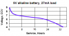
Consider the LED drain on the 9Vbty.
 
Any recommendations/tips for cutting the veroboard to size?

Use an special soldering iron cutting tip ??
A saw?
Stanely knife?
 
Any recommendations/tips for cutting the veroboard to size?

Use an special soldering iron cutting tip ??
A saw?
Stanely knife?

You can use a steel rule and Stanley knife, score deep, especially the copper side so that you dont rip the tracks off when you break the pcb.

Use a 3 or 3.3mm dia drill to remove the cut track/holes, [dont bore thru the board]

You can use a junior hacksaw to cut the board, make sure the copper track ends are cleaned off, use a fine file.

Clean the board copper before assembly.
 
I haven't seen the original blue epoxy-fiberglass Veroboard for years. It was unbreakable.
The tan-coloured phenolic stuff warps and breaks easily.
I use epoxy-fiberglass "Veroboard" from China now.
 
The original epoxy-fiberglass Veroboard was a dark blue colour. The sheets were about 50cm long and about 10cm wide (34 strips).
I looked for a pic in Google Images but couldn't find one.
 
The original epoxy-fiberglass Veroboard was a dark blue colour. The sheets were about 50cm long and about 10cm wide (34 strips).
I looked for a pic in Google Images but couldn't find one.

I also used to have that blue expoxy stripboard, not seen it for ages.

Its far better than SRBP, which can delaminate in damp conditions and it easily broken if you are a bit rough.


EDIT: its not blue, but its expoxy Vero PtNo: 01-27568

**broken link removed**
 
Last edited:
I am trying to reduce the 9V battery to 2.2 to allow a 2.2VDC LED to work.

I came up with whats in the diagram. This is giving me 2 VDC when measured on my DMM however when I attach my LED it does not work.

Any ideas as to why?

Or is there a better solution to do this (maybe one resistor)?

Thanks
 

Attachments

  • LED.JPG
    LED.JPG
    10.6 KB · Views: 142
Further investigation appears to be indicating that I need:

R1: 500 OHM
R2: 150 OHM

To compensate for the load (LED).

Is this correct or am I off track? :eek:


I am trying to reduce the 9V battery to 2.2 to allow a 2.2VDC LED to work.

I came up with whats in the diagram. This is giving me 2 VDC when measured on my DMM however when I attach my LED it does not work.

Any ideas as to why?

Or is there a better solution to do this (maybe one resistor)?

Thanks

Hi,
I did query this LED.:)

Consider you have an LED with a 2Vdp and you want to run it from a 9Vdc supply.
This means you must drop 7V in a series resistor.
You say you want 20mA thru the diode [ I would suggest thats to high for a 9Vbty]
anyway Rseries = 7V/0.02 = 350R say 390R

For 10mA Rs = 7/0.01 = 700R say 680R

Do you follow OK?


EDIT: You only need one resistor.

If you must have a 20mA LED [wasteful for the battery] the use a 390R
 

Attachments

  • Led.jpg
    Led.jpg
    7.9 KB · Views: 134
Last edited:
Thanks Eric,

I am using a push button, with an LED, I know it might be an additional drain on the battery, but I am not too worried about this for now, I may not need the switch nor the LED later on.


Here is the datasheer for the LED:

Page 435.

https://www.electro-tech-online.com/custompdfs/2008/11/0900766b8002e7a6.pdf


Hi,
I did query this LED.:)

Consider you have an LED with a 2Vdp and you want to run it from a 9Vdc supply.
This means you must drop 7V in a series resistor.
You say you want 20mA thru the diode [ I would suggest thats to high for a 9Vbty]
anyway Rseries = 7V/0.02 = 350R say 390R

For 10mA Rs = 7/0.01 = 700R say 680R

Do you follow OK?


EDIT: You only need one resistor.

If you must have a 20mA LED [wasteful for the battery] the use a 390R
 
Power sensor signal conditioning

And one thing that I am surprised about is that when I use my DMM is show about 8.23 VDC, and that when I use a 390 OHM resistor.


I intially used a similar method to workout the resistor size needed but when testing did not show 2VDC I thought I was doing something wrong.


Thanks Eric,

I am using a push button, with an LED, I know it might be an additional drain on the battery, but I am not too worried about this for now, I may not need the switch nor the LED later on.


Here is the datasheer for the LED:

Page 435.

https://www.electro-tech-online.com/custompdfs/2008/11/0900766b8002e7a6-1.pdf
 
Last edited:
And one thing that I am surprised about is that when I use my DMM is show about 8.23 VDC, and that when I use a 390 OHM resistor.


I intially used a similar method to workout the resistor size needed but when testing did not show 2VDC I thought I was doing something wrong.

hi,
Looking at the datasheet for the PB it states it has a inbuilt resistor for the LED.!
No external resistor required.

Did you get 12V version of the P/B?
 

Attachments

  • esp01 Nov. 22.gif
    esp01 Nov. 22.gif
    48.2 KB · Views: 147
Last edited:
No Unfortunately I got the 2.2VDC one which does not have a resistor.

Although I had a choice of either, but I thought the 12VDC one will not work on my 9VDC battery, now thinking about it I think it would have been perfect.

I tried both the 390R and 680R and both seem to work. I am thinking that the 680R is better to use but I do not know which one will put more strain on the battery though.


hi,
Looking at the datasheet for the PB it states it has a inbuilt resistor for the LED.!
No external resistor required.

Did you get 12V version of the P/B?
 
I tried both the 390R and 680R and both seem to work. I am thinking that the 680R is better to use but I do not know which one will put more strain on the battery though.

hi,

Use Ohms Law to answer that problem: Icurrent = Volts/Resistance

So 9Vbty - 2.2Vdp = 6.8V [ to drop across the resistor]

Gives:
I1 = 6.8/390R = 17.4mA
I2 = 6.8/680R = 10mA..

If the battery was only driving the LED, with a 680R it would last twice as long compared to a 390R.

I would have thought the LED would be bright enough at 10mA.:)
 
Indeed. I did not notice a clear visible difference in brightness between the two resistors.

I will certainly go with 680R in this case.

Ohms law is not a problem but rather using it with the correct figures is :D

Thanks a lot.

I am making a complete enclosed PCB with bananna connectors and USB connector and p/b with LED.

Bananna for the clamp which uses them.
USB for the output and +v input.
and push button to switch on/off .

:)

Almost there ;).

By the do you recommend using single or multicore cable connectors for the Veroboard? I was thinking of using the phone cables that are single core but the color does not help, I do have multicolored multicore cable but I am reluctant to use it becuase it is normally used for audio (I think). So I ordered single core cable but until it arrives I am twiddling my thumbs :D


hi,

Use Ohms Law to answer that problem: Icurrent = Volts/Resistance

So 9Vbty - 2.2Vdp = 6.8V [ to drop across the resistor]

Gives:
I1 = 6.8/390R = 17.4mA
I2 = 6.8/680R = 10mA..

If the battery was only driving the LED, with a 680R it would last twice as long compared to a 390R.

I would have thought the LED would be bright enough at 10mA.:)
 
Last edited:
By the do you recommend using single or multicore cable connectors for the Veroboard? I was thinking of using the phone cables that are single core but the color does not help, I do have multicolored multicore cable but I am reluctant to use it becuase it is normally used for audio (I think). So I ordered single core cable but until it arrives I am twiddling my thumbs
hi,
For the light current, low voltage work phone wire or multicore is OK.

I have old multicore cable 7/0.2mm which I strip off the outer overall pvc sheath and screened braid, that I use for wiring from switches, banana,batteries, plugs etc.
For pcb board links single core [phone] wire is best.
 
Last edited:
Your vision's response to brightness is logarithmic to allow you to see a wide range from the light from a candle to sunlight. Therefore an LED's brightness does not look much different when its current is halved or doubled.

Your 9V battery measures "only" 8.23V when it is loaded because it is running down.
A 9V battery doen't have much power. Look at its datasheet from the website of a battery manufacturer like Energizer:
1) It is 9.0V when new.
2) With a 27mA load its voltage drops to 8V in about 1 hour.
3) Its voltage drops to 7V in about 7 hours but then the current is less.
4) Its voltage drops to 6V in 22 hours but then the current is very low.
 

Attachments

  • 9V alkaline, 27ma.PNG
    9V alkaline, 27ma.PNG
    7.7 KB · Views: 144
Thanks. I will consider adding an external power adaptor.

As it stands this will not be running for long time. Having said that I would not mind finding out the actual total load on the battery once all have been put together, and have a test run until battery runs out and see the impact on the AD736 and CA3140 outputs.


Your vision's response to brightness is logarithmic to allow you to see a wide range from the light from a candle to sunlight. Therefore an LED's brightness does not look much different when its current is halved or doubled.

Your 9V battery measures "only" 8.23V when it is loaded because it is running down.
A 9V battery doen't have much power. Look at its datasheet from the website of a battery manufacturer like Energizer:
1) It is 9.0V when new.
2) With a 27mA load its voltage drops to 8V in about 1 hour.
3) Its voltage drops to 7V in about 7 hours but then the current is less.
4) Its voltage drops to 6V in 22 hours but then the current is very low.
 
Hi Eric,

I've been going over the circuit of the CA3140 to amplify the AD736 signal and I drew a blank on how the cicuit below was decided upon (Please ignore question in the image ):

pots-gif.23701


What I would like to understand is why did we go with a 4k7 resistor at pin2 and Why the 10k at pin 3.

I understand the voltage at 4k7 will be 4.5v so applying a 4700 ohm resistance will generate 0.96mA.

And for pin 3 at a maximum of 1VDC we get 0.1mA.

So what is the significance of choosing those particular ones as opposed to say 10k at 2 and 20k at 3 for example, how would this have impacted the output. For instance.. would i get the same results provided i adjust the 20k VR correctly?

The whole diagram (proposed is what was built):

diagram_new-jpg.23883


Thanks a lot for your time.


Regards


Charbel
 
Status
Not open for further replies.

Latest threads

Back
Top