im constantly amazed by how easy for you to design something like that, but how did you arrived with the values of resistors? cause that is my main problem with my design, i have to defend it and explain why i used that or those particular resistors.
We were TAUGHT about electronics. It looks like you were not taught about electronics.
1) Simple arithmatic calculates the output currents.
2) The datasheets for the transistors gives the minimum, typical and maximum current gain.
3) Ohm's Law then simply calculates the resistor values.
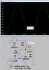
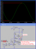
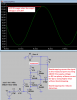
With a 9V supply (or a plus and minus 4.5V supply) the output swing into an 8 ohm speaker will be about 7V p-p which is 3.5V peak.
Then the peak output current is 3.5V/8 ohms= 438mA.
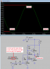
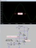
The minimum current gain of a TIP31 power transistor is about 38 at 438mA so its maximum base current is 438/38= 11.5mA.
Then the current sink for the output transistors should supply 11.5mA. But it doesn't because it was designed for 0.7V/100 ohms= 7mA. So the curcuit will work fine with output transistors with typical or better current gain but will not work if the current gain is less.
That is why I always design a circuit to work with ALL current gains of a transistor (especially the minimum current gain), not just typical current gain.
If you make a single circuit then the current gain of your transistors is not known unless you measure them. Their current gain might be low, typical or better.
If you simulate a circuit with typical transistors then their current gain is typical.
Then your circuit might work only with typical or the best transistors. Then it will not work with transistors that have passing but lower gain.
The negative feedback resistors values are also very simple.
One resistor provides base current to the input transistor so Ohm's Law simply calculates its voltage error and its value. THEORY simply calculates the other resistor value for the voltage gain you want.