scripted13
New Member
Then the output power will be very low and little transistors can be used.
When the little 9V alkaline battery is brand new the maximum output voltage swing into an 8 ohm speaker will be about 6V p-p. Then the peak current in the output transistors is 3V/8 ohms= 375mA.
6V p-p is 2.1V RMS then the output power is only 0.55W like a cheap clock radio.
You can use 2n4401 NPN and 2N4403 PNP output transistors.
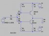
Unclejed's circuit will work very well but its has transistor Q6 connected upside down. It is supposed to be an emitter-follower.
His circuit has a dual polarity supply so it will need biasing at its input and three added coupling capacitors.
Also the battery needs a bypass capacitor.
A high input impedance preamp will be needed as I showed.
cant i alter the resistors so that i can have a better output? how did you know the output without even knowing the resistors used in the circuit? cant i use two npn transistors? lets say we will stick to my original circuit, cant i have at least 10 v p-p out put to supply for the speaker?
 . Battery life would be improved over class-AB.