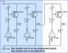
I'm definately not an electrical engineer, but I figured something this simple was within my limited grasp. I studied the schematic for my PIC programmer, researched via google, and found out the parts are ok substitutions. I want to be able to switch the 12v coming from my programmer board via the Vpp1/MCLR line to any one of multiple PIC chips. My programmer board does exactly that, but when I try to duplicate it on my breadboard, it fails. It works fine if the supplied voltage is 5v, but when I apply the 12v, it supplies 12v at the output no matter what state the input has. Could someone take a look and tell me what they see? Vpp3 is the output, and I'm using RD0 from my PIC to control the circuit's on/off state.
Continue to Site