Continue to Site

Welcome to our site!

Electro Tech is an online community (with over 170,000 members) who enjoy talking about and building electronic circuits, projects and gadgets. To participate you need to register. Registration is free. Click here to register now.

  • Welcome to our site! Electro Tech is an online community (with over 170,000 members) who enjoy talking about and building electronic circuits, projects and gadgets. To participate you need to register. Registration is free. Click here to register now.

Please review design and error of electronic ignition

Status
Not open for further replies.

easy.rahil

Member
hello experts,
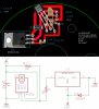
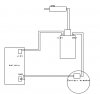
i m trying to make an electronic ignition like pamco and got similar design from a friend, i make homemade pcb for this schematic but output is coming without using magnet(added an led to check output and its constant on). can anyone guide me?
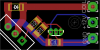
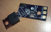
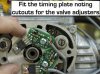
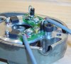
PCB
compare.jpg IMG_20180524_103453.jpg IMG_20180524_103453.jpg

I m using MLX90217 geartooth sensor in place of A1250 Hall sensor.
U1 is IRGB14C40L mosfet.

Also let me know if there is any other hall sensor i can use

please let me know what is the actual problem
 
You do not appear to have a bias magnet?

As I understand it, a setup such as that uses a small permanent magnet behind the sensor to provide a fixed field.
The sensor picks up the changes in the field caused by the iron rotor moving near it.

See page 6 of the data sheet here:
https://www.melexis.com/-/media/files/documents/datasheets/mlx90217-datasheet-melexis.pdf
i have used hall effect sensors without and bios magnets a nd rotor uses a magnet to change field and give output when magnet comes front of hall sensor. i dnt k now about this gear tooth sensor. if anyone can give a light on it.
 
The one you are already using is a high precision one that is perfect for the application you need it for.
It just needs a suitable small magnet to work as shown in it's data sheet.

If you need it to operate with a magnet rather than an iron or steel rotor, then the 3144 type should work without any bias - but it's positional accuracy may not be so good.
 
application is electronic ignition for motorcycle and i can not use bios magnet on board so i m using simple magnet in an aluminium rotor. suggested Hall Latch was A1250 but sadly i did not find any in here. so if i can get any other suitable Hall effect sensor, 3144 is conmanly popular, but as u said accuracy may compromise so i m asking any other hall sensor with accuracy.
 
The one you are already using is a high precision one that is perfect for the application you need it for.
It just needs a suitable small magnet to work as shown in it's data sheet.

If you need it to operate with a magnet rather than an iron or steel rotor, then the 3144 type should work without any bias - but it's positional accuracy may not be so good.
hello, i m using A3144 hall sensor but result is still same..added a red led on output and it turn on without any magnet nearby nor affected by any magnetic field. what i m doing wrong?
 
The hall sensor is "off" (so output open circuit) with no magnet. That's allowing the resistors to turn on the FET.

You need another transistor stage between the sensor and the FET gate to invert the operation and turn the FET on when a magnetic field is present.
 
Show us the complete circuit, with all component values.
I have got this circuit from this page:
**broken link removed**

here is updated image with parts placement and part number:

A Quick note: i m using power supply of 6V ( is it possible to give error of this reason?( do i need minimum 12V for this?
 

Attachments

  • NEWCIRCUIT.jpg
    NEWCIRCUIT.jpg
    401.9 KB · Views: 528
added a red led on output and it turn on without any magnet nearby
You don't show how that is connected in the circuit or whether a current-limiting resistor was also included.
i m using power supply of 6V ( is it possible to give error of this reason?( do i need minimum 12V for this?
Maybe. My browser reports the web-site hosting the datasheet pdf as insecure, so I haven't checked the spec.
 
You don't show how that is connected in the circuit or whether a current-limiting resistor was also included.

Maybe. My browser reports the web-site hosting the datasheet pdf as insecure, so I haven't checked the spec.
you may check the datasheet of mosfet here:
here is the original images of respected designer pcb and placement:
 

Attachments

  • irgs14c40l.pdf
    160.2 KB · Views: 240
  • ignitionboard.png
    ignitionboard.png
    13.3 KB · Views: 277
  • ignitionassembled1.png
    ignitionassembled1.png
    1,015.7 KB · Views: 404
Last edited:
According to the datasheet the IGBT is a logic-level input type so should switch on fully when using a 6V supply. However, Vce is specified as ~1.2V, so that leaves only ~4.8V across the coil. You may get a weaker spark than you'd like.
The IGBT has a built-in pull-down resistor on the gate, so it should switch off providing the Hall sensor output is switched low by the magnet.
Have you tried reversing the magnet?
 
yes i tried revering the magnet. problem is that it is not recognize the magnet as output is coming constant even without using magnet.
 
output is coming constant even without using magnet.
That is what it should do. With no magnet the Hall sensor output will be pulled high by R1, so the FET will turn on and the coil will be energised.
 
That is what it should do. With no magnet the Hall sensor output will be pulled high by R1, so the FET will turn on and the coil will be energised.
But it should not give any groung output without a magnet comes near hall sensor, sensor gives signal when magnet comes front of hall and thn mosfet release ground connection to coil.
 

Attachments

  • point.jpg
    point.jpg
    37.4 KB · Views: 266
I think we have a communication problem. Try this test :-
1) Disconnect the coil from the circuit for now.
2) Power the circuit (with 6V, or even a PP9 battery).
3) Connect a Voltmeter between the Hall sensor output and ground.
4) Measure the voltages with and without a magnet close to the Hall sensor.
5) Post the voltage readings.
 
But it should not give any groung output without a magnet comes near hall sensor

Exactly - so the FET is turned ON all the time by the resistors to positive power, and only OFF when the sensor detects a magnet and shorts the gate to 0V.

That's why I said a few answers back that you need an extra transistor stage to invert the signal between the sensor and FET.

Remember that the sensor has an open-collector type output - it's not low/high logic, it's off (open circuit) or on (shorted to 0V)
 
Last edited:
Exactly - so the FET is turned ON all the time by the resistors to positive power, and only OFF when the sensor detects a magnet and shorts the gate to 0V.

That's why I said a few answers back that you need an extra transistor stage to invert the signal between the sensor and FET.

Remember that the sensor has an open-collector type output - it's not low/high logic, it's off (open circuit) or on (shorted to 0V)
FET giving output regularly with and without magnet. not turning on at any stage either magnet is there or not. tried reversing magnet poles too.
As per my knowledge it should work like that a sensor gives output when magnet comes nearby and a currunt limiting resistor pulls up output signal of sensor thn signal goes to FET PIN 1 and it opens and connects the Drain(PIN2 and Source(PIN3) so HT coil complete the function and gives spark.
My circuit acts like it is already connected Pin2 and 3.
is the PCB i design is good as per schematic aatached?
Part i m using is good?
Tantalum Capacitor is Good?
DO WE really need a DIODE between drain and source? Pin2 and Pin3?
A3144 hall sensor works similar to A1250?
If PCB is exactly the same of basic schematic thn perhaps some parts are misbehaving or bad.
Do we really Need R2 in place? as we already using R1 to pull up signals.

i m not using this on my bike yet i m using my desk to test function with a 6V power supply and output i m using a LED attached.
Circuit is clone of PAMCO ignition. Pic attached.:
 

Attachments

  • plate.jpg
    plate.jpg
    50.4 KB · Views: 306
  • Hold Down Screw.JPG
    Hold Down Screw.JPG
    48.6 KB · Views: 264
Last edited:
Looks like the head of the hold-down screw in those pics is shorting to a pcb trace?
Did you try the test I suggested?
 
Status
Not open for further replies.

Latest threads

New Articles From Microcontroller Tips

Back
Top