Continue to Site

Welcome to our site!

Electro Tech is an online community (with over 170,000 members) who enjoy talking about and building electronic circuits, projects and gadgets. To participate you need to register. Registration is free. Click here to register now.

  • Welcome to our site! Electro Tech is an online community (with over 170,000 members) who enjoy talking about and building electronic circuits, projects and gadgets. To participate you need to register. Registration is free. Click here to register now.

Please help to design simple OFF-delay timer

Status
Not open for further replies.

ymmy

New Member
I’m completely new at this and need help to design simple low 3-6 voltage OFF-delay timer.
Here is what I need:
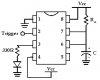
1.Power supply would be 3-6volts
2.Timer should not have any buttons and switches, once power applied to the circuit it should activate relay for about 3-5 second and then release relay contacts by cutting off power from relay (time not very critical and can vary plus minus few seconds)
I know it can be accomplished by using single transistor and few capacitors & resistors but I’m never done it on my own plus I’m unable to find something similar on internet. I’ll be appreciated if someone can help or point to right direction.
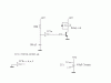
_________
-------- | 3-5Sec |
3V-6V | Timer | ----->Relay-----Load
-------- | Circuit |
 
No problem.
 

Attachments

  • relaydelay2.GIF
    relaydelay2.GIF
    1.6 KB · Views: 1,039
Sebi, Thank You a Lot!!! :D 
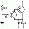
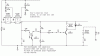
Few more questions: Do I still have to use diode and second transistor to amplify signal in case I’ll use 5V Opto relay such as ‘LCA120’ datasheet here: **broken link removed** I think led inside relay draws very little current and probably one transistor would be enough but I’m not sure. What transistor type (maybe part number) would you recommend if I’ll buy it from ‘RadioShack’ store.
 
Last edited by a moderator:
See the post by John Sorensen dated 9 April 2004 in the Electronic Projects/Design/Ideas/Reviews forum.

However, I would use a CMOS Schmitt Trigger IC such as the 74C14, 40106, etc. And you could use a 0.1 uF capacitor and 10k resistor in lieu of those shown.

Len
 
Sebi said:
No problem.

Sebi, I’ve done your design and it works great but now I have another problem. It’s takes very long time to discharge capacitor (used 220mF in order to keep relay On for about 3 sec) so I can use switch again. I’ve tried 200k resistor across capacitor but relay never goes off…seem like capacitor will not be fully charged so I increased to 2Meg and relay start to work but I still have to wait couple of minutes before I can use circuit again. Any idea what can be done now? I need something to be ready again within few seconds after disconnecting power supply ..in other words capacitor should be discharged almost immediately after power removed.
 
ymmy said:
Sebi said:
No problem.

Sebi, I’ve done your design and it works great but now I have another problem. It’s takes very long time to discharge capacitor (used 220mF in order to keep relay On for about 3 sec) so I can use switch again. I’ve tried 200k resistor across capacitor but relay never goes off…seem like capacitor will not be fully charged so I increased to 2Meg and relay start to work but I still have to wait couple of minutes before I can use circuit again. Any idea what can be done now? I need something to be ready again within few seconds after disconnecting power supply ..in other words capacitor should be discharged almost immediately after power removed.

Fit a reverse biased diode across the 68K, anode to the capacitor - when you remove the power the capacitor will discharge through the diode via the HT rail - it will actually keep the circuit powered until the capacitor discharges.
 
Thanks Nigel Goodwin but don't know where to get 'reverse biased diode'.
My local Radioshack does not have this animal...
I've start to believe this project sound like building nuclear power station, second day and nothing done so far :roll:
Also, tried schematic below which gives 2sec long output pulse when power applied (if pin#2 connected to Vcc) but again have to wait forever to discharge cap.
 

Attachments

  • LM555ckt.jpg
    LM555ckt.jpg
    28.4 KB · Views: 1,310
Thanks Nigel Goodwin but don't know where to get 'reverse biased diode'.
My local Radioshack does not have this animal...

Ymmy,
"Reverse biased" refers to how the diode is used, not the type of diode. He means it "points up" across the resistor.

Ha ha
Reminds me of the time I sent Wife to Radio Shack to get a "555 Timer" and they showed her the alarm clocks.

What a bunch of flunkies. "We have questions; they don't know what the hell we're talking about."

Wife now *loathes* to go to RS for me, but when she must I send along with her a sample of something similiar so she can say, "It looks like this."

j.

Not busting on ymmy, but rather the rocks that are supposed to know such things for their "job."
 
As requested by PM, here is a circuit for you. This assumes that the relay will operate on 6 Volt. If, not, check the relay data and alter the supply voltage to suit.

The IC pin connections can be found on the internet. eg. try www.discovercircuits.com

Len
 

Attachments

  • Ymmy_s_circuit_205.gif
    Ymmy_s_circuit_205.gif
    3.2 KB · Views: 977
Latest developments…Thanks to Nigel Goodwin for suggestion of using diode across 68k resistor. Now capacitor fully discharged within 8-12 sec! Much better if compare to few min before. I would say it acceptable for me now and I’m the happiest person in the world at least for today :mrgreen: Now I just can’t resist to try one more design kindly provided by ljcox. John Sorensen, thanks for pointing to 'reverse biased diode' issue..hehe Yeah, RatShack people sometimes don’t see the difference between Tv and computer monitor., not to mention electronics components :p
Thank you guys :!: :!: :!:
 
What to do with those extra gates? Use them to discharge that capacitor "right now." Note that the 74HC14 must be powered from "upsteam" of the switch in order to be in control.

j.

BTW, do you have CircuitMaker? It's easy and free for experimenting.
 

Attachments

  • Off_delay.gif
    Off_delay.gif
    8.6 KB · Views: 863
Wow, ljcox's circuit is a BomB! Because small cap needed, discharge time takes probably less then 1 sec., and ready to be used instantly every time after On/Off power cycle. Also it appears to be physically smaller due to very small 0,39uf cap dimensions. John Sorensen, thank you for your schematic, looks very cool!!! but I think its overkill in my case. Also, just downloaded CircuitMaker and will try learn how to use it properly before 30 days trial expiration.
 
Not to knock other's suggestions, the problem with large resistances in circuits like this is 1) the current into the the NOT gate is non negligible and 2) the high impedences can make the circuit susceptible to EMI/RFI/finger touches. Probably will work fine, though.

fwiw,
j.
 
John Sorensen said:
Not to knock other's suggestions, the problem with large resistances in circuits like this is 1) the current into the the NOT gate is non negligible and 2) the high impedences can make the circuit susceptible to EMI/RFI/finger touches. Probably will work fine, though.

fwiw,
j.
Maybe you right, circuit provided by ljcox is not a perfect design from point of view very picky hardware engineer…I don’t know But it works under test for the second day and went through few thousands of Off/On cycles without single failure. Transistor version failure rating was like 30% if switch activated several times within very short period of time.
 
John Sorensen said:
Not to knock other's suggestions, the problem with large resistances in circuits like this is 1) the current into the the NOT gate is non negligible and 2) the high impedences can make the circuit susceptible to EMI/RFI/finger touches. Probably will work fine, though.

fwiw,
j.
I disagree with points 1 & 2. The data sheet for the 74C14 CMOS Schmitt Trigger states that input current is about 5 nA at 15 Volt.

This means an error of about 50 mV which is negligible, particularily in view of the wide tolerances of CMOS Schmitt Trigger threshold levels.

On point 2, the impedance at the input to the Schmitt is relatively low due to the capacitor to gnd. So EMI/RFI should not be a problem. Finger touches would alter the timing though, but that is not serious issue in practice.

However, I agree that it is not an ideal timer and this circuit should only be used in non critical applications. I used one to provide a 3 minute delay in my garage door opener circuit to control the light. It has been working successfully for several years. The delay is only approximate, but it is not critical.

Len
 
But the datasheet I am looking at says input current to the gate can be as high as 100nA, which is not negligible across a 10Meg resistor in a 5V circuit, so obviously it can vary from part to part.

As for the second point, I was merely mentioning that a stiff circuit is generally better than a high impedence one, if you can spare the power and (in this case) the space. I agree that the cap adds an amount of filtering. A finger touch across a (say 1206) resistor can be (easily) an order or two less than the 10Meg.

I know we're not shooting for the text-book example of a timer, but I though it was worth mentioning.

fwiw,
j.

BTW, who said I was very picky?
 
John,
I don't know which data sheet you are lookingat, but I used the 74C14 which states 5 nA typical at 15 Volt.

The constructer can choose between a high resistor and accept the disadvantages you allude to, or use a larger capacitor (thus possibly an electrolytic) and proportionally smaller resistor.

Len
 
Status
Not open for further replies.

Latest threads

Back
Top