Continue to Site

Welcome to our site!

Electro Tech is an online community (with over 170,000 members) who enjoy talking about and building electronic circuits, projects and gadgets. To participate you need to register. Registration is free. Click here to register now.

  • Welcome to our site! Electro Tech is an online community (with over 170,000 members) who enjoy talking about and building electronic circuits, projects and gadgets. To participate you need to register. Registration is free. Click here to register now.

Please help me with my project. Our defense is in two weeks from now. :(

Status
Not open for further replies.
upload_2017-11-26_8-1-5.png

Now I understand you want it to look like this. And maybe a red, and green LED next.
I know how to make the circle with 32 LEDs.
I know how to make a 7 segment count.
I do not know how to make it count like this:1,13,36,24,3,15.....There is probably a simple way. I don't see it.

Because your time is short I think you should make it count 1,2,3,4,5,6,7...... Better to have something working then to have nothing.
 
Look at what other people have done:
upload_2017-11-26_8-11-50.png

I know this is not what you want. BUT
Look at the LM555 IC.
When you push the button the IC oscillates fast. When you release the button the IC oscillates slower and slower then stops. (100k pot + 91k + 8.2k 220nF makes the oscillator) The voltage on top sets the speed. The energy stored on 330uF25V keeps the oscillator running after the switch is opened.
I think this is how to make the button and oscillator.

One block is done.

What is next?
 
What kind of parts can you get.
74LSxx like 74LS33
or CD40xx example CD4051.
The sequence for a roulette wheel is not 0,1,2,3,4,5,6,7...... Is it OK for it to count 1,2,3..??
 
What kind of parts can you get.
74LSxx like 74LS33
or CD40xx example CD4051.
The sequence for a roulette wheel is not 0,1,2,3,4,5,6,7...... Is it OK for it to count 1,2,3..??
yes it is okay to count like that

will you please look at this circuit

it generates a number 0 to 99. its like a decade counter but both of them starts at a different time so it became like a random number generator. my only problem is that how will i make the upper 7 segment to generate to 0 to 3, and the other 7 segment, to generate 0 to 9 if the upper segment is 0- 2. and if the upper segment is 3, the lower 7 segment will generate only to 0-2.

i think if i'll make it like that it would only generate 0-32
 

Attachments

  • Screenshot (1).png
    Screenshot (1).png
    57.5 KB · Views: 227
I don't like the way it works.
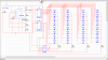
I would use only one "555" oscillator.
Make the two 7490s count as one.
(clock to CKA, QA to CKB, QD to CKA2, QA2 to CKB2,)
Counts from "00" to "99". But you want it to count 00 to 32. 32=0011,0010
Add a gate that detects 32. xx11, 0010. (x=don't care) When 32 then reset the two counters (will happen on the next clock)
I think this will work xx11, xx10 ??? You need to think about this.
> 0011,0000=30, 0011,0001=31, 0011,0010=32, so look for xx11,xx1x or a 3 input AND gate.

I thought the black/red was as simple as odd/even or just QA1. ???

----------------------------------
7447:
The RBI pin will blank when "0".
Without RBI a zero ="00"
With RBI on one IC, zero = " 0" or "0 "
----edited----
what CAD program are you using?
The green LED is xx00,0000, = green
OR
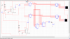
You could take the "32" signal and delay it by one count.
>use a D FF. Clock to CKA1, Data from "32" This will cause 32 delayed by one clock to be at time "00"

The random number is a function of when you pull your finger off the switch. If you add the function in post #22 you will get some "random" after the finger is removed. The count will go around several times more after the finger is removed.
 
Last edited:
sorry for the late reply guys, i just talked to my professor, and he told me that i can do it this way, i have to look for a circuit diagram in the internet of a roulette with 32 leds, in which each led that would light up will have a corresponding value that would be displayed in the 7 segment led, and he said that i can do that using a 5 bit decoder
 
oh sorry "must"

could you help me :(( im trying to do the led part in multism but it just doesnt work :(
 

Attachments

  • Screenshot (3).png
    Screenshot (3).png
    68.6 KB · Views: 238
1) Your 74LS00 will smoke and burn when you power it with 10V. It is normally powered with 5V. Then the LM555 and CD4017 ICs also must use 5V.
2) The CD4017 ICs do not have their Vss pins connected to ground.
3) With a 5V supply the CD4017 ICs have a fairly low output current (about 2mA) causing the LEDs to be dim. Why not use modern powerful 74HC4017 ICs and replace the old TTL 74LS00 with a modern 74HC quad Nand gate?
 
Velvet,
You have two different types of parts in the schematic. The CD4017 parts will work over a very wide range of voltages. The 74ls00 is really a 5 volt only part. In the CD40xx family there is a part that will work. Same function.
 
Velvet,
You are using a CD4017 which counts from 0 to 9 (10 states). The way you have it connected, states 8 and 9 will come up and there will be no LEDs lit. You should change to a CD4022. It has outputs 0-7 (8 states)
 
1) Your 74LS00 will smoke and burn when you power it with 10V. It is normally powered with 5V. Then the LM555 and CD4017 ICs also must use 5V.
2) The CD4017 ICs do not have their Vss pins connected to ground.
3) With a 5V supply the CD4017 ICs have a fairly low output current (about 2mA) causing the LEDs to be dim. Why not use modern powerful 74HC4017 ICs and replace the old TTL 74LS00 with a modern 74HC quad Nand gate?

theres no 74hc4017 ic in the simulation im using :( thank you i have connected vss to the ground now
 
Velvet,
You are using a CD4017 which counts from 0 to 9 (10 states). The way you have it connected, states 8 and 9 will come up and there will be no LEDs lit. You should change to a CD4022. It has outputs 0-7 (8 states)
is that the reason why my simulation is not working? because of the 4017 ic i've used? i cant find any 4022 here in multism
 
Multisim is a stupid old sim program. Most of us use modern LTspice.
The 74HC4017 will also smoke and burn with a 10V supply, look in its datasheet at its maximum allowed supply voltage.
 
theres no 74hc4017 ic in the simulation im using
not 74hc4017. That is a 5 volt only part. That did not solve your problem.
CD4017.
------------------------------------------
or run the entire project from 5 volts and get rid of the 10 volts.
------------------------------------------
is that the reason why my simulation is not working? because of the 4017 ic i've used?
There could be 100 reasons......

Start out simple.
Does the LM555 work?
Next connect one CD4017. Does it work?
0___-_____
1____-____
2_____-___
3______-__
-----------------------------------------
I can make the CD4017 work like a CD4022. First we need go get you simulation working.
 
Status
Not open for further replies.

Latest threads

New Articles From Microcontroller Tips

Back
Top