Continue to Site

Welcome to our site!

Electro Tech is an online community (with over 170,000 members) who enjoy talking about and building electronic circuits, projects and gadgets. To participate you need to register. Registration is free. Click here to register now.

  • Welcome to our site! Electro Tech is an online community (with over 170,000 members) who enjoy talking about and building electronic circuits, projects and gadgets. To participate you need to register. Registration is free. Click here to register now.

Pioneer DC-Z92 Stereo Double Cassette Tape Deck Amplifier - Transformer problem

Status
Not open for further replies.
Hi,

The black thing with A & B pointing to it is a relay. (I am assuming this controls the power to the main transformer.)
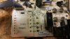
Oh, sorry................I thought it was something else (a voltage convertor) from the details on the outside !! And the fact it is inline with a fuse !
I will have to be more careful !


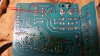
There are other transformers on the net for the other voltages.

But this would mean a total of 3 transformers for all the voltages.

Would this be acceptable?

Yes it will have to be...............do you mind telling me what they are please

Thank you,
John
 
Yes it will have to be...............do you mind telling me what they are please

Sure. It will be an interactive exorcise. I will do an initial list and perhaps Les can assist to find suitable transformers. Then you can review the list and see if the transformers suggested will physically fit.

spec
 
OK, fine, thank you
No sweat John.:)

As Les says, we like people who answer our questions and are polite.

The cassette/amplifier may be more critical because than your other equipments because transformers can introduce hum into the signal lines so, in this case, as well as functional tests we will have to do some tests on the audio to ensure that no hum has been introduced. This will apply especially to recording and playing back cassette tapes.

Very often the cure for induced hum is to change the position and orientation of the transformers. And if push comes to shove, it may be necessary to put the transformers in a metal case.

But my feeling is that there should not be a problem.

spec
 
Hi Les & Spec,
I have been reading through your comments again, and trying to learn as much as possible.

Look like the top transformer is:
(1) Primary: 240V RMS
(2) Secondary #1: 4V RMS
(3) Secondary #2: 32V RMS
(4) Secondary #3: 12V RMS


If the primary of the top transformer has gone open circuit, you could put 4V RMS from another source (transformer), across the 4V terminals and measure the other seondary voltages.

If there is room in the Hi Fi for an extra transformer then you could feed 12 volts AC into bottom winding (That supplies the 12 volts for the relay and 5 volts for the electronics.) If you try this disconnect the 4.4 volts output (For the display filaments) in case the voltages from the original transformer are different to the assumed values.

The primary circuit has gone "open circuit".
So reading what you have both said, do I understand that if I placed a 12vAC source onto the bottom winding, I will get voltages out of the middle and top secondary windings, but we are not sure what the voltages would be ?

I understand how the bottom winding supplies 12 volts for the relay..........but how does it supply 5 volts for the electronics ?

Thank you,
John
 
Hi John,
We have only estimated that the bottom winding will be about 12 volts. We know that the top winding is 4.4 volts so if we apply 4.4 vots to that winding (With no load on the other windings.) we can measure the voltages from the other windings. (Also as we probably don't have exatly 4.4 volts available we would maybe apply 3 volts to it. In that case we would then multiply the votages that we measured by 4.4/3 to find out what they should be.) If our estimate of 12 volts is correct and we apply 12 volts to it from another source we will cet the correct voltages from the other two windings. I suggested disconnecting the 4.4 volt connection before trying this in case the voltage we get from the 4.4 volt winding is high and damages the filaments in the display. If we find the 4.4 volts is high or low we can then calculate what the "12V" winding realy is. It is the middle winding that supplies the relay. (And the higher voltage for the display.) The lower winding supplies the 5 volts for the electronics.

Les.
 
Thank you Les for the explanation. I understand much better now.

I would do better to remove the transformer completely from the board to do these tests.
Currently I do not have any suitable transformers, all the transformers I have are rectified to produce DC (and I have lots of them).
Have never tried breaking them open and removing the rectifier. Is that a good idea, or even possible ?

Which would be better for the test.............3vAC (if 4.4vAC cannot be found) OR 12vAC ?

John
 
Hi John,

With a transformer the voltage relationship of the winding holds, so that you can apply the specified voltage to any winding and you will get the related specified voltage across all the other windings. Take an example of a mains transformer as follows:
(1) primary winding= 240V
(2) secondary winding #1=1V
(3) secondary winding #2=2V
(4) secondary winding #3=4V
(5) secondary winding #4=8V
(6) secondary winding #5=16V

Obviously if you apply 240V to the primary you will get the specified five secondary voltages in the normal way.
But you can also apply, say 1V, to secondary #1 (correction- thanks Les) and you will get the specified voltages on all the other windings, including 240V on the primary. In fact, you can make an inverter from a standard 12v + 12V secondary mains transformer. So, with some electronics, you can convert 12V DC (say from an automobile) battery into 240V AC.

You can also connect in series any, or all of the secondary windings, to give other voltages.
For example, if you connected all the secondaries together in series you would get a total voltage of 1V+2V+4V+8V+16V= 31V, or any other combination of windings.

In practice, there are a few factors to take into account because real transformers are not perfect, but the theory still holds.

spec
 
Last edited:
Hi John,
Removing the transformer from the board would be a good idea. I think the ideal way would be to connect 9 or 10 volts AC to the winding that we are calling the 12 volt winding. I have taken plug in power supplies appart but it really depends how confident you feel about doing so. Some plug in power supplies are screwed togeter others are glued or welded. Chose one that is screwed together. Aim for one rated about 9 volts output. Do not use one of the modern light weight ones as they do not have a normal mains tranformer in them. When you are testing treat it as if there is 230 volts on the mains input connections just in case the break in the primary makes contact again.
Edit. I've just read spec's post. He has made a typing error where he says "1V, to secondary #2 and you will get the specified voltages on all the other windings. its hould have been 1 V to secondary 1 or 2 V to secondary 2

Les.
 
Last edited:
I've just read spec's post. He has made a typing error where he says "1V, to secondary #2 and you will get the specified voltages on all the other windings. it should have been 1 V to secondary 1 or 2 V to secondary 2.
Corrected- glad you are checking Les.:)

spec
 
Hello again !

Thinking a little more on this subject........................is my conclusion correct please ?

If the transformer is:
(1) Primary: 240V RMS..................winding on open circuit
(2) Secondary #1: 4V RMS.............winding OK
(3) Secondary #2: 32V RMS.............winding OK
(4) Secondary #3: 12V RMS.............winding OK

And I isolated the Primary from the main board, leaving all the secondaries in place.........All that is needed is a new 12vAC transformer (with a high enough watt rating), and the existing transformer (with the open circuit Primary) will do the rest.
By the rest I mean the 32vAC and 4vAc

Thank you,
John
 
Hi John,
Before buying transformers it will be worth checking that the filaments on the displays have not been blown by the overvoltage. On this unit measure the resistance between the pins on the connector that plugs into the board with the faulty transformer. (These are the pins that are fed from the 4 volt winding.) I think from memory that the are the second and third down on the connector at the top left of the schematic in post #3. It's worth doing the same test on the microwave. I suspect that these are displays made just for those products so you would probably not be able to obtain spares. I wouldexpect a resistance reading around 70 ohms. One other thought. Look on ebay for anyone selling these products on ebay. Even if they are faulty there is a chance that the transformers may be OK. (Unless they are being sold by someone that lives very close to you.)

Les.
 
Morning John,

Thinking a little more on this subject........................is my conclusion correct please ?

If the transformer is:
(1) Primary: 240V RMS..................winding on open circuit
(2) Secondary #1: 4V RMS.............winding OK
(3) Secondary #2: 32V RMS.............winding OK
(4) Secondary #3: 12V RMS.............winding OK

And I isolated the Primary from the main board, leaving all the secondaries in place.........All that is needed is a new 12vAC transformer (with a high enough watt rating), and the existing transformer (with the open circuit Primary) will do the rest.
By the rest I mean the 32vAC and 4vAc
What you say is exactly correct... theoretically and it would probably work practically. But I would advise against that approach because the reliability of the original transformer has been badly compromised by the voltage surge. Using new transformers is thus advisable.

The technique of energizing one of the secondary windings and measuring the rest is only suitable, in this case, for establishing, definitely, what the original transformer voltages are.

spec
 
Hi Les & Spec,

I have tried my best to establish some more information.

I have removed the transformer from the board, and while doing so have noticed that a filament (probably acting as a fuse) has burnt. It is a filament in line with the glass fuse with the power into terminal 2 on the primary. See photo.
The other larger filament (to the right of the broken filament ) is inline with the glass fuse and goes into terminal 1 on the primary. The larger filament is not burnt out.
Hope this makes sense !
So there is no connection to terminal 2 primary...........open circuit.

With the transformer removed from the board :

Primary: Terminals 1-2 = zero ohms
Primary: Terminals 2-4 = 20 ohms
Primary: tried all other combinations...........nothing, zero ohms.

Secondary: Terminals 1-2 = 15 ohms
Secondary: Terminals 3-4 = 50 ohms
Secondary: Terminals 5-6 = 20 ohms

ON THE BOARD ITSELF on the secondary terminals with the transformer removed:
Resistances everywhere except Terminals 1 & 2...........open circuit.

Spares are no longer available anywhere.............have tried !
Also have looked everywhere for second hand equipment similar and identical to mine on ebay and other sites.........so far have found nothing which corresponds.

Many thanks

John

PS: will write a separate post for the Daewoo microwave oven
 

Attachments

  • 20161110_103417.jpg
    20161110_103417.jpg
    195.1 KB · Views: 277
  • 20161110_095509.jpg
    20161110_095509.jpg
    146.6 KB · Views: 277
  • 20161110_093813.jpg
    20161110_093813.jpg
    237.4 KB · Views: 279
Thinking this through now that I have established that Terminal 1 and 2 cannot be the primary windings on the transformer.........could they be terminal 1 to terminal 4 (for 240 volts) OR terminal 2 to terminal 4 (for 220v).
I don't really understand this
It looks like the little filament which is broken saved the winding Terminal 2 to Terminal 4 on the primary.
However there is nothing (infinite ohms) between terminal 1 and 4.............the larger filament did not burn !

What are your views please ?
 

Attachments

  • 20161110_095509.jpg
    20161110_095509.jpg
    146.6 KB · Views: 255
  • 20161110_103417.jpg
    20161110_103417.jpg
    195.1 KB · Views: 252
Hi John,
The things that you are calling filaments are wire links to set the unit for a mains voltage of either 220 or 240 volts. ONLY ONE OF THEM SHOULD BE INSERTED. As the resistance between 2 and 4 is 20 ohms (That is the 220 volt connections .) I would expect the resistance between 1 and 2 to be about 2 ohms. There would be 20 volts between these two points. (About 10% of the 220 volt part of the winding so about 10% of the resistance. It looks like the primary is not open circuit as we thought. Have you checked the fuse on that board ?

Les.
 
Hi Les,
Have just checked again.
On the transformer (off the circuit board) Primary Terminal 1 (240VAC) is open circuit with all terminals on the primary side.
On the transformer (off the circuit board) Primary Terminal 2 (220VAC) with Terminal 4 (0vAC) has a resistance of 20 ohms.

Now on the circuit board (with the transformer removed)............... there is a resistance of about 10 ohms because of the thicker wire link.

The fuses on the circuit board are all fine. It was the first thing I checked

Thanks,
John
 
Status
Not open for further replies.

Latest threads

Back
Top