Continue to Site

Welcome to our site!

Electro Tech is an online community (with over 170,000 members) who enjoy talking about and building electronic circuits, projects and gadgets. To participate you need to register. Registration is free. Click here to register now.

  • Welcome to our site! Electro Tech is an online community (with over 170,000 members) who enjoy talking about and building electronic circuits, projects and gadgets. To participate you need to register. Registration is free. Click here to register now.

PICAXE not working?

Status
Not open for further replies.

fouadalnoor

Member
Hello guys,

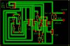
I am trying to program and run my PICAXE 08M chip on my test board to check if a program I created works. For some reason the program downloads into the pic fine, but when I try to test it, it doesn't show anything (like the output is just low)?

The program is as follows:

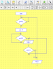
; output 0 for motor
; input 1 is gas on
; input 2 is flame on

main:
if input1 = 0 then goto main

wait 10

flamecheck:
if input2 = 1 then goto flamecheck

high 0

motorcheck:
if input1 = 0 then low 0 else goto motorcheck endif

goto main


_______________________


The above code is programmed using the PICAXE editor found here:

The chip (08M) is found here:


Do I need to add the additional 22k and 10k resistors to the circuit ust to test it as well?

Hope you can help!

Fouad.
 
This question would likely be better served in the Micro controller sections of the forums.

The 10K and 22K ohm resistors are required to program the chip as well as run the chip I believe. However, if you just want to run a simulation of the code in the programming editor you don't even need the chip. Your code leaves much to be desired. What exactly are you trying to do? I ran the code in the programming editor with and without a chip. I also loaded your program onto a chip.

For example you have this:

Code:
flamecheck:
if input2 = 1 then goto flamecheck

If Input2 is High the program is just going to sit there? I don't get the logic of things?

Also when posting code samples please use the code tags as above. It makes it easier to read.

Ron
 
Last edited:
You fool (smile) if you look at your circuit design you are not even using pin 1 and 2 as inputs it is pin 3 and 4 you are using as inputs.
Output 2 goes to the fet.

You need to change your code to suit the pins used.

input pin4 goes to the switch
input pin3 goes to the 311
output pin 2 goes to the fet

Pin 0 is not used
pin 1 is not used

Also note you have pin3 pulled high and you have pin4 pulled low with resistors.

The right pins in the code might just solve your problem.

Pete.
 
Last edited:
Pete

Where is this circuit design? I only see two links in the original post. What am I missing here?

You fool (smile) if you look at your circuit design you are not even using pin 1 and 2 as inputs it is pin 3 and 4 you are using as inputs.
Output 2 goes to the fet.

Ron
 
Thanks Pete and now I remember the threat. Sitting here early morning and thinking what the hell is he seeing that I am not seeing?" Alas, now it all comes back to me. :)

Ron
 
Okay guys, this is what I sent to SABorn, maybe you can help out?

Hey,

Okay so I have now tested the PIC on its test board (supplied with the 22k and 10k resistors) and it seems to work fine. When its on the board it works okay as well (I just used code to turn the output ON and checked it, then re-programmed it and made the output always LOW and that worked too). Now For some reason when I test the whole circuit, I get the motor being ON all the time. It makes no sense...

When the output of the PIC is low then the FET is supposed to be OFF and the motor is OFF. But for some reason its always on...

I dont know if this will help but when I measure the voltage across the motor terminals when I program the PICs output as high (always) I get 4.57v when I program the output to be low (always) I get the motor terminals to be 4.05v

do you think the FET is not working? how can the motor terminals be high when the base of the FET is low?

Hope you can help!
 
You may want to try using a pulldown resistor on the gate of the FET. Maybe around 10K and see what happens.

Ron
 
I know that sucks. Just test the theory of a pulldown with some external wires if possible. 10K from gate to ground (common). I would be curious what the gate shows compared to what you had.

Ron
 
I found out I may have put the FET (2n7000) the wrong way around where the drain was connected to ground so I have now changed that. I have 2 main problems

1. The chip does not do what the code says (unless I just say that the output is HIGH all the time or LOW all the time)
2. There is voltage across the motor terminals (around 2.8v) when the FET's base is 0 (no output voltage from the PIC)

For the time being, the motor wont actually start when the voltage is 2.8v (as it runs on 3-5v I think) so I can ignore that for now. I just want to make sure I have the PIC working according to the code and when that's done I can trouble shoot further.

If you guys help me check I have the circuitry for the PIC correctly set up I would be very grateful!
 

Attachments

  • 1.jpg
    1.jpg
    198.7 KB · Views: 166
Last edited:
As for adding a pulldown all i do for things like that is to solder it to the bottom of the board, one of the advantages you will find with using wide tracks as you have done, is you can always drill a hole in the track to add a missed component later, no need to remake the board.

As i said send me your code so i can check there is nothing in the code that is causing the problem, as it could be causing the output to switch on and off at a fast rate and effectively PWM the motor and if so, yes you will only see a reduced voltage at the motor.

I see nothing wrong with the circuit.

Pete.
 
Okay, I just re-tested it and I am getting the following results:


Code:
main:
if input4 = 1 AND input3 = 0 then high 2  ;gas and switch ON, wait 12s and Motor ON
endif 
if input4 = 0 OR input3 = 1 then low 2  ; gas OR switch OFF, Motor OFF - if the flame is on in the middle 
endif 
goto main

I get no output (output2) voltage when the input3 of the PIC is 4.57v and input4 is 0.10v.

At this point the FET shows:

The voltage on the 2n700 FET Base is 0v (as expected)
The voltage on the 2n700 FET Drain is 0.03v (not expected)
The voltage on the 2n700 FET Source is 0v (as expected)

The voltage across the motor terminals is (I must say it kept going down..): 0.81 (and counting down...- maybe because of the 10uF Cap?)

Before soldering the 10k resistor on let's see if changing the code might help...I suspect I was not waiting long enough for the cap to discharge and thought that the voltage across the terminals was actually constant. If changing the code works and the terminal voltages just discharge then I think we may have solved the problem?!

PS: I actually removed the 12s wait in the actual code as I just want to see it working first. The way I may do it is just use a flow chart in the PICAXE Editor as shown in the attached image.
 

Attachments

  • 3.png
    3.png
    31.1 KB · Views: 169
Last edited:
Im not 100% sure on this but do feel your code should be layed out a little different, even though it might not show a syntax error i would advise it to be done this way.

A application should not follow the "then" on the same line unless it is a direct command like a goto, or gosub or the " : " is used in between.

Some syntax will work without fault and others will not when all included on the same line.

I also would add some pause statements for testing to slow down any strange operations so they may be detected.

Code:
main:

if input4 = 1 AND input3 = 0 then 
high 2  ;gas and switch ON, wait 12s and Motor ON
pause 200
endif 

if input4 = 0 OR input3 = 1 then 
low 2  ; gas OR switch OFF, Motor OFF - if the flame is on in the middle 
pause 200
endif 

goto main

I would also remove the 10uf cap as it dont really need to be across the motor, after testing you can always put it back is you want but it will make the measurements easier without it in circuit.
Pete.

Well tried it with the cap on and I still get the same result..no output from the pic.

I then changed the code to the following:

Code:
main:
 
if input4 = 1 AND input3 = 0 then 
low 2  ;gas and switch ON, wait 12s and Motor ON
pause 200
endif 
 
if input4 = 0 OR input3 = 1 then 
high 2  ; gas OR switch OFF, Motor OFF - if the flame is on in the middle 
pause 200
endif 
 
goto main

I now get the output high all the time...
 
Ok this would seem there is a problem with the input side.

What is the voltage on input4 pin when the motor should be on.
What is the voltage on input3 pin when the motor should be on.

Pete.
 
Ok i think i see the problem............
Input 3 is pulled high via a resister and input 4 is pulled low by the resistor.
So the code is ass about.

Try this....
Code:
CODE REMOVED TO SAVE CONFUSION

Pete.
 
Last edited:
Then i might be backwards to.

Can you tell me is the output from the 311 meant to turn the motor on or is it turn the motor off.
What is the switch meant to do.
I forget the actual procedure how this function now please refresh me.

Pete.
 
Status
Not open for further replies.

Latest threads

Back
Top