Continue to Site

Welcome to our site!

Electro Tech is an online community (with over 170,000 members) who enjoy talking about and building electronic circuits, projects and gadgets. To participate you need to register. Registration is free. Click here to register now.

  • Welcome to our site! Electro Tech is an online community (with over 170,000 members) who enjoy talking about and building electronic circuits, projects and gadgets. To participate you need to register. Registration is free. Click here to register now.

Pic18F4550 stepping sequence.

Status
Not open for further replies.

heroic

New Member
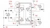
Hello, I am trying to get a motor, PM35S-048, to rotate using PIC18F4550, and L293D. The problem i am facing is that even thought i used the circuit schematic given in hte datasheet of l293d, the motor does not rotate...

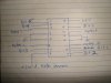
The problem is either in the stepping sequence, or in the the schematic i am using.

Here is the source code i am using...

Code:
#include <p18f4550.h> 
#include <delays.h> 

void main (void) 
{ 
int i,j; 
TRISC=0;
PORTC=0b00000000;
while(1){
PORTC=0b00010100;
Delay1KTCYx (240);/*200ms*/
PORTC=0b00110101;
Delay1KTCYx (240);/*200ms*/
PORTC=0b00101011;
Delay1KTCYx (240);/*200ms*/
PORTC=0b00001010;
Delay1KTCYx (240);/*200ms*/
}
}


and i have also attached the datasheet that contains the schematic i am using...
 

Attachments

  • l293d_2.pdf
    204.4 KB · Views: 378
try:
ADCON1 = 0x0F; //Place before while(1) statement

EDIT:
I noticed no config information. Are you setting config bits?
 
Last edited:
well, this code made the motor rotate a bit, and adcon will just give digital output, right? in case of analog signal also the l293d should rotate the motor though inefficiently... i hope i am right.
 
How is port C connected to the L293?
Which diagram are you referring to?
What kind of motor is it, stepper?

Mike.
 
yes the motor is stepper, and i have specified everything in the post above... the schematic is exactly the one used in the datasheet of l293d...

the portc.0 bit is connected to pin 15 of l293d.

and now i am using this code...


Code:
#include <p18f4550.h> 
#include <delays.h> 

void main (void) 
{ 
int i,j; 
TRISC=0;
PORTC=0b00000000;
ADCON1 = 0x0F;
while(1){
PORTC=0b00110000;
Delay1KTCYx (240);/*200ms*/
PORTC=0b00101000;
Delay1KTCYx (240);/*200ms*/
PORTC=0b00000110;
Delay1KTCYx (240);/*200ms*/
PORTC=0b00000101;
Delay1KTCYx (240);/*200ms*/
}
}
 
Last edited:
one more update: the motor rotated for a while, that is it did take some steps. and then there was was just some sound...
 
how are you setting the PIC clock? and Config info? I dont see it in above code maybe it doesnt know whether to use a internal or external clock and freezes up when you try to do something. it just gets lost without OSC settings.
 
yes the motor is stepper, and i have specified everything in the post above... the schematic is exactly the one used in the datasheet of l293d...

the portc.0 bit is connected to pin 15 of l293d.

Nope, checked again and I can't find any stepper diagram that shows port C.

You tell us how 1 bit is connected and expect us to guess the other 5. Even though none of the stepper diagrams show 6 driving signals.:confused:

Mike.
 
I am using the delay commands to generate the step...


@pommie: here is the schematic with pins numbers mentioned.
 

Attachments

  • pins.JPG
    pins.JPG
    52.8 KB · Views: 268
@pommie:well, yes. therefore i had to make changes to stuff, i connected each coil of the stepper to one of the output pins and the common one to 24V supply. and i made changes to the stepping sequence also... if you want i can give you an exact schematic of what i am using... give me a minute.
 
Status
Not open for further replies.

Latest threads

New Articles From Microcontroller Tips

Back
Top