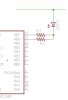
I want to see if I'm on the right track with this. I need a varied voltage leaving the PIC dependant on which way the SPDT switch is set.
And, what if I have a 3 way switch, can I just add another OUTPUT PORT >> RESISTOR >> DIODE?
Do I even need the DIODEs?
Thanks!
**broken link removed**
And, what if I have a 3 way switch, can I just add another OUTPUT PORT >> RESISTOR >> DIODE?
Do I even need the DIODEs?
Thanks!
**broken link removed**
")