Continue to Site

Welcome to our site!

Electro Tech is an online community (with over 170,000 members) who enjoy talking about and building electronic circuits, projects and gadgets. To participate you need to register. Registration is free. Click here to register now.

  • Welcome to our site! Electro Tech is an online community (with over 170,000 members) who enjoy talking about and building electronic circuits, projects and gadgets. To participate you need to register. Registration is free. Click here to register now.

PIC based high-resolution cap meter

Status
Not open for further replies.
hi,
I have discussed this problem with Roman, this is his reply.
E.

It's more likely they are seeing process variations (manufacturing changes) in the PIC 16F628 internal comparator. The important thing to remember is that the cap meter is very linear, so if there is an error it only requires a tweak to that 10k resistor. Like putting a trimpot in series with it, and and after it is adjusted once it will be correct throughout all cap ranges.
-Roman
 
AVE...

Mr. Black, could you please make slight modification to the code, so it would output measurements by serial? I accidentally murdered my LCD and I wanted to test if it actually works at all...

EDIT:
Generator works, but LCD is dead. You could use RB0 for zeroing, and then RB1 and RB2 for serial interface with USART module...
 
Last edited:
Mr. Black,

I assembled the capacitance meter kit from Alex and technically it works fine. A few issues though:

I did trim resistance (P1) to 10.0001k ohm (using a high resolution HP multi meter) and assumed I have a perfectly calibrated capacitance meter. First I zeroed the meter and then
I used two precision 1,000 pF 1% caps (provided by Alex) and they measured 1037pF and 1038 pF. What is wrong, the caps or the meter. The caps shouldn't be more than 1010 pF (1%). If the meter needs calibration, do I trim P1? But that gets off the 10k ideal. Or do I use another method?

When measuring Large Caps I've noticed that the meter starts with a value and after that slowly creeps lower, forever it seems. What's the problem, Should I wait until it has stabilized? I stopped waiting after 10 minutes.
If I have the right understanding of this meter, you should zero the meter with no cap, measure the precision cap and trim the resistance to get the right reading.
 
One more issue. To test the meter I made up two precision capacitors, each made up of several polystyrene and mica caps, with both caps measuring exactly 10,000 pF (matched within 0.01% and less than 1 pF difference) according to the Roman Black cap meter. I then measured these caps on my old 3 1/2 digit capacitance meter where one tested 10.3 nF and the other tested 10.4 nF (1% difference). I measured several times and any impact of test leads can be ruled out. Why is there a difference between the caps? Are the meters using different methods of measuring capacitance leading to different results? Can one meter measure more than just capacitance? Which one is more correct? Can someone please provide a possible explanation.
 
One more issue! I did recently discover another issue with the cap meter. Until now I have measured single capacitors and trusted the meter. Then I had to bundle a few caps in parallel and I discovered a problem. I have two capacitors, each measures 1.024 nF on the RB meter. I wire them in parallel and expect the measurement to be 2.048 nF but the Roman Black meter measures 2.020 nF! I did the repeat the procedure several times and also on three other DMM's and although they had only had 3 1/2 and 4 1/2 digits they measured the bundled cap correctly at exact twice the value of a single cap at 2.048 nF.

This indicates to me that the RB meter is not linear and can not be trusted no matter how many digits it displays. Is the formula properly programmed in the PIC? What is going on?
 
1.5% accuracy on a low cost bit of kit like this is not bad really ;)

In that case why bother with a 7 digit display.

I did some more testing by measuring bundles from two up to ten capacitors with the same nominal value of 10 nF. The sum of all ten caps measured individually with the RB meter was 98.031 nF. The value of the bundle was 95.570 nF, about 2.5% lower than the sum of the individually measured caps (measured with the same meter). Interestingly, the percentage difference increased with the size of the bundle where the bundle always measured lower then the sum of the individuals. Two caps in parallel measured only 0.74% lower than the sum of those two individual caps.

I repeated this experiment using two low cost DMM's (with capacitance function). Measurements were here of course slightly different due to small differences in calibration vs the RB meter. However here the bundles measured about the same value as the sum of the individual caps, given small random variations. No systematic variation could be detected here.

Given this test, I can only draw the conclusion that the RB meter measures fairly accurate around the value for which it was calibrated (1,000 pF in my case), but for values at 10 or 100 times the calibration capacitance the error becomes very large (Several percent). This error seems to be systematic and grows proportionally to the value of the cap measured. Note that this meter is commercially marketed for accuracy of 1% or better. I can only suspect the cause to be either the PIC program or the hardware since the theory seems to be OK.

I would highly appreciate getting comments to the above from Roman Black.
 
Having designed test equipment:
1) It is a problem when the user does more testing than the designer.
2) "1.5% accuracy on a low cost bit of kit like this is not bad really ;)"
3) Looking at the circuit I think there could be an error as you get away form the calibrated point. Probably positive one direction and negative the other direction.
4) I see errors when the capacitor leaks. (large caps) This is normal.

I have what is probably this meter. (or a clone of it) I got a kit with all parts and a box years ago. I have BNC posts in the PCB board and "grabbers" in the BNC posts so I don't have wires leading to the capacitor to test. Two inches of wire (and its placement) makes a great difference at the pF level. I use the meter mostly to measure capacitance between traces on PCBs and to measure capacitance between wires. (very small values) My $2000.00 meter does not like to compare 1.1pF and 1.2pF values.

I have a large number of silver mica capacitors less than 10pF. Even the manufacture does not know how to measure 2.2pF accurately.

My DVM uses a "one-shot IC" and measures the time of the pulse to guess the capacitance. I like the idea of making an oscillator to measure the capacitance. I have used a grid dip meter to measure capacitance which is much like this little meter, but I have to use a calculator and frequency counter.

Answer: Yes there are many ways to measure capacitance. AND A capacitor is more complicated than just a "C". There are Rs and Ls involves. On my big $$$ meter I can choose what frequency to measure at. 1mhz, 100khz, 10khz.......... And the reading is a little different.

Interesting testing! Lots of hard work! Thank you!
 
Looking at the section "Precision Period Measuring" on RB's website I notice that all calculations are done with integer variables. Given the PIC's limitations with integer math I'm wondering if not overflow and truncation issues may be at play here. This would be more noticeable with caps larger than 10nF where intermediate results hit the roof due to multiplying with 1000 (in order to avoid calculating with decimals) and division with a low number for "consecutive periods". This would explain the results I'm getting. Maybe a PIC allowing for more than 32-bit integers or a range selector (with a suitable resistor for each range) could be a remedy.

Again, I would highly appreciate Roman Black's comments to this issue and also an upload of the source code for the program
 
Last edited:
Sorry I did not answer this earlier but I don't visit the forum much these days. :)

If I understand you right you measured 2 caps separately, then after you joined them together they measured different to the sum of the 2 values?

There could be a number of reasons for that. The most obvious thing is that with two caps in parallel they are still charged by the ONE 10k resistor, so now they are being charged and discharged with HALF the current used in the single cap tests. That gives you half the self heating (affects cap temp co), and might also cause issues with the cap internal ESR etc. Those physical issues might explain why the caps measured differently.

Another thing that has caught me out in the past when testing caps was after joining caps by soldering their short legs together they were quite warm and that easily changes their capacitance value by a couple of percent. Maybe that explains your data?

If you think the cap meter oscillator is not linear you can test this very easily by putting a decent frequency meter on the comparator output, and if the oscillator is linear then the displayed cap value will read half when the freq is doubled (or other ratio depending which 2 caps you use in the test). It passed that test well when I tested it.

To look at the linearity or the oscillator; the cap is charged and discharged between two voltage thresholds, and because the PIC has a regulated 5v supply these thresholds should remain the same even with different caps. The charge/discharge is through the PIC internal pin fets and the 10k resistor. Those resistances should remain the same with different caps. Then there is a fixed error from stray PCB capacitances and the small internal cap etc, but this remains the same and is zeroed out with the button. So ultimately the only thing that changes the osc freq after that is the capacitance (and internal resistances) of whatever cap you connect to the test probes. It is also affected slightly by small capacitances of your hands and the position of the test wires etc (a few pF), which can be noticeable when testing very small caps but usually doesn't matter. However you should still make sure your test leads are short and secured from movement.


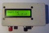
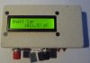
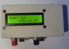
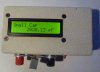
Probably the main thing to remember is that this is a cheap simple high RESOLUTION cap meter, not a high accuracy meter. The high resolution is great for comparing caps, or seeing capacitance change as you heat a cap, or seeing small cap values or changes from moving wiring etc. After an initial calibration by tweaking the 10k resistor it should measure caps better than 1%, and might even be better than 1% straight out of the box (that depends how closely your PIC internals match my PIC). Caps are normally 10% tolerance or worse, so that is plenty of accuracy.

With most caps the temperature coeficient is so high that they will change 1% or more in cap value even with finger heat or ambient temperature changes, or self heating when used in an oscillator. If you wanted to make a very high accuracy cap meter you need to use carefully controlled fixed current for charge and discharge and keep the cap in a fixed temperature container (to negate ambient temp changes and self heating issues). That is well out of the scope of a capacitance meter using one PIC and four resistors... ;)

Regarding the math I used in the software it is very accurate. The osc freq (period) is measured by summing a great number of contiguous periods until the total sample is in the millions so the native resolution of each measurement is very high (less than 1 part per million error). Then the math routines scale the data before and during the calcs so it JUST fits in 32 bit variables, so any errors there are very small in the order of 1 part per billion or so. (That gives much better ratio accuracy than if I had used 32 bit float math.)
 
Roman Black, thanks for your detailed response. When I purchased this cap meter kit I wanted a meter that could match capacitors with the same nominal value as close as possible. With this purpose in mind your meter is a great tool since it can provide up to 7 digit measurement.

Recently I did build a electronic notch filter where the design requires two capacitors where one should be exactly twice as large as the other. The efficiency of the filter depends on the relationship 2 / 1 to be as close as possible. In my case I wanted to match a 10nF cap to a 20nF cap. The absolute value is less important than the 2 / 1 relationship that should be as exact as possible. My goal was to get a match <0.1%. When I, using your meter, discovered that the sum of two individually measured caps was about 1.2% larger than the measurement of the composite of these two caps I started investigating this matter a little bit further and made a post on this website.

I agree with the theory behind the design and your explanation of possible reasons for the results I am getting. I think are all valid and are well taken. However they do not explain my problem. For the sake of this post I am providing a few attached pictures. The meter is built into an enclosure with screw terminals. First, all my measurements were made with the cap securely clamped in these terminals and leads were never used. Second, the caps were never soldered together so any heat from soldering can't be a factor. Third, my hands were far away from the meter for the readings. Fourth, I recently used a borrowed high end HP/Agilent cap meter to measure two single caps, 10nF and 100nF. Using the 10nF cap I calibrated the RB meter to measure exactly the same capacitance as the HP meter. However on the 100nF cap the HP meter measured several % higher than the RB meter indicating that at least one of these two meters isn't linear.

Since all frequency determining components, capacitor, resistors are fixed and any stray capacitance was zeroed out my conclusion was that the problem must lie with the PIC itself, the PCB layout or the software.

I have tested this meter using various types of caps and values, with or without test leads, soldered and unsoldered caps, but still the results are basically the same. Attached are a few pictures from measuring two 1% precision calibration caps (as provided by RH Electronics). The pics show the meter calibrated before measurements, the measurements for the two individual caps and finally both caps measured together. The value of the sum is 2044.18 pF vs. 2020.13 pF for composite measurement, a difference of about 1.1%. Measuring the same two caps on the HP meter provided the exact same result for the sum of the two caps as for the composite.
 

Attachments

  • RB1.JPG
    RB1.JPG
    116.6 KB · Views: 539
  • RB2.JPG
    RB2.JPG
    98.9 KB · Views: 498
  • RB3.JPG
    RB3.JPG
    114.4 KB · Views: 448
  • RB4.JPG
    RB4.JPG
    122.7 KB · Views: 514
Last edited:
Hello Mjölnir,

As always..... Questions and more questions....But when someone has a solution I do
not see them. Did you get any further.
I have the project on a breadboard and 1% acc. is possible.
Keep in mind, that your other meter uses probably a fixed measurement frequency
and the RB meter uses different frequencies when measuring parr. caps.
When I use my own meter on different frequencies, I get different readings.

The 10.00K is only valid, if the clock frequency is on the spot and
the trigger levels are on the spot.

If you want better accuracy, you have to do a couple of things.
1. Use a very stable reference voltage. (Buried zener with opamp < 0.01%)) If the ref. is
not stable, the ref points will vary thus the frequency will vary.
2 The 1/3 and 2/3 reference points. I think this is hard to get them right, because if you match
the two 1k5 resistors from + to ground that problem is not solved.
The R-voltage on the comparator output should go from +5V and from ground, but they are probably not.
I have to find a meter to check. {Also offset and frequency related response time}
And if you change one resistor, it affects the trigger point of the other.
It will not be easy, but it can be done.

Pls let me know what you achieved this far.
My Dutch is much better than my English,
but I hope you understand what I mean.
 
Last edited:
Hi Roman,

Thanks for sharing this ("fempto-meter" ¿?) useful tool. Using a breadboard is worst than wiring a cow, but finally already made. Precision is better than my radio shack multimeter (or near it). Any way, I made it to use it in the construction of touch pads sensors and maybe water level sensors too. And since I'll measure the changes in capacitance, not capacitance itself, this tool is quite perfect.
Having only 2KBytes in the 16F628A is too low to make some complex math.
Here is a pic measuring 823 polyester cap.

Although not sure about your code. I will try to read it and rewrite :lurking: the measuring/counter part to sense the touch pads.
Thank you!
 

Attachments

  • cap_meter.jpg
    cap_meter.jpg
    1.7 MB · Views: 372
Last edited:
Hi there,
There are some thing that can be solved with little or no effort.
Zero drifting is obviously greater with ceramic caps than polyester. So for the 271 cap is better to choose a polyester cap or maybe tantalum, if this value can be found with any of this caps, maybe the 22pF caps for the 16Mhz osc too, although not sure about this.
Soldering the 16Mhz metal can to GND really breaks the zero dancing, making the drifting more softly and predictable. This can be noise introduced by my spaghetti-messy non pcb :sorry:.

In the other hand, I also add a pull up resistor (10k) to the cal button. To left pins floating can increase current and maybe introduce noise.
 
Status
Not open for further replies.

Latest threads

New Articles From Microcontroller Tips

Back
Top