;*******************************************************************
;                           16F877 PWM Program
;*******************************************************************

		include	"p16f877.inc"

		errorlevel	-302
		radix	dec

	__CONFIG _CP_OFF & _DEBUG_ON & _WDT_OFF & _BODEN_OFF & _PWRTE_ON & _HS_OSC & _LVP_OFF & _CPD_OFF

		cblock	20h
OnTime:2
OffTime:2
		endc

		cblock	71h
int_work
int_status
int_pclath
		endc

		org     0h
		nop
		goto    start
		nop
		nop

		org 	04h
interrupt	movwf	int_work
		swapf	STATUS,W
		movwf	int_status
		bcf	STATUS,RP0
		bcf	STATUS,RP1
		movfw	PCLATH
		movwf	int_pclath
		clrf	PCLATH

		btfsc	PORTB,0
		goto	TurnOff
; turn on the output and write the on time
		nop;		delay to make both path identical
		bsf	PORTB,0
		bsf PORTB,1;<<<<<<<<<< Break Point
		movfw	OnTime+1
		movwf	CCPR1H
		movfw	OnTime
		movwf	CCPR1L
		goto	DonePWM

TurnOff		bcf	PORTB,0
			bcf PORTB,1;<<<<<<<<<< Break Point
		movfw	OffTime+1
		movwf	CCPR1H
		movfw	OffTime
		movwf	CCPR1L
DonePWM
		bcf	PIR1,CCP1IF;	reset special event trigger interupt

		movfw	int_pclath
		movwf	PCLATH
		swapf	int_status,W
		movwf	STATUS
		swapf	int_work,F;	swap to file
		swapf	int_work,W;	swap to work
		retfie


start		bsf	STATUS,RP0
		bcf	STATUS,RP1
		bsf	STATUS,IRP;	all indirest access is to 100h - 1ffh
		 movlw	(0<<NOT_RBPU|0<<INTEDG|0<<T0CS|0<<T0SE|0<<PSA|B'000'<<PS0)
		movwf	OPTION_REG
		movlw	b'11111100'
		movwf	TRISB
		bcf	STATUS,RP0
		movlw	(b'01'<<T1CKPS0|0<<T1OSCEN|0<<NOT_T1SYNC|0<<TMR1CS|1<<TMR1ON)
		movwf	T1CON;		enable timer 1
		movlw	low(5000)
		movwf	CCPR1L
		movwf	OnTime
		movlw	high(5000)
		movwf	CCPR1H
		movwf	OnTime+1
		movlw	low(45000)
		movwf	OffTime
		movlw	high(45000)
		movwf	OffTime+1
		movlw	(0<<CCP1X|0<<CCP1Y|b'1011'<<CCP1M0);	enable special event trigger on CCP1
		movwf	CCP1CON;
		bsf	STATUS,RP0
		bsf	PIE1,CCP1IE;	enable CCP1 interupt
		bcf	STATUS,RP0

		movlw	(1<<GIE|1<<PEIE|0<<T0IE|0<<INTE|0<<RBIE|0<<T0IF|0<<INTF|0<<RBIF)
		movwf	INTCON;		enable Peripheral interupts

Loop
		goto	Loop

END

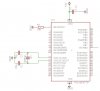
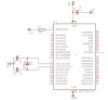
") See attachement if interested in my diagram.
See attachement if interested in my diagram. 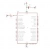
 .
.