Continue to Site

Welcome to our site!

Electro Tech is an online community (with over 170,000 members) who enjoy talking about and building electronic circuits, projects and gadgets. To participate you need to register. Registration is free. Click here to register now.

  • Welcome to our site! Electro Tech is an online community (with over 170,000 members) who enjoy talking about and building electronic circuits, projects and gadgets. To participate you need to register. Registration is free. Click here to register now.

Peltier circuit Ideas

Status
Not open for further replies.

bryan1

Well-Known Member
Hiya Guys,
I just got my 6amp 60 watt peltier from Oatleys yesterday :D
and the idea is to make up a water cooler for my shed. I'll be running it off my 16 volt nife battery bank which is on floating voltage most of the time. Now I've searched google and the forum for idea's but only a few things seem feasable. I can run it via PWM if I keep the frequency above 2kHz, the heatsink I'm going to use is an old pentium 1 heatsink with a fan bolted to the back of it so that should take care of the heat dissapance.
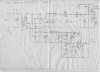
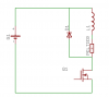
Now I'll only be cooling 4 litres of water at a time and have an 11 litre bottle ontop. Now I'm a bit stuck on the circuit to use the idea is use a 15 volt zener to clamp the voltage as the battery bank can go higher than 15 volts, then use a small pic for the pwm feeding a mosfet to supply the correct current. If my idea is way off let me know :oops: also if someone could supply a few peltier circuits that I could study it will make my life a bit easier.

Cheers Bryan :D
 
I have built and used Many Peltier devices ove the past 25 years.

A Pentium Heatsink is Definately NOT BIG ENOUGH, even with a fan.
If you want Effiency, You need to keep that Hot Side, Really Cool.

I would Not Recommend PWM.

Use a Thermal Detection Circuit to turn it Full On and Full Off as Necessary to maintain the temperatue required.

USE Lots of Insulation on your Water Tank.

A Zener is Not Appropriate for that kind of Supply Current.
Possibly a diode or two in Series, to just Drop the Voltage a Bit.
Or Better yet, Get a Better regulated Charger.
 
I would have to agree there with chemelec, Peltier devices do not like to be switched on and off rapidly. Besides, there is no point in doing so since temperature variation for a mass of 4 litres of water are going to be slow anyway.
I had built an air cooling device (for medical experiments to condense water vapour out of breath) and this used a 0.75 deg C/W heatsink on the hot side, cooled by a powerful compact 240V fan.
You will need very good insulation between the hot and cold side, there is some good info on the net about this - will try to dig up the URL later for you.
My circuit ( don't have access to a scannerhere) is basically a full bridge power supply, the peltier module being fed via a MJ1106 darlington transistor which in turn was controlled by a temperature sensor.
The darlington had a 8 ohm/25W resistor in parallel which fed the peltier on lower power during the off cycle, thus giving it a soft supply.
I remember tinkering with the resistor values for a while to get the device cycling slowly at the desired temperature, since the cold side was just an alu block 50x50x25mm with air ducts inside.

Klaus


chemelec said:
I have built and used Many Peltier devices ove the past 25 years.

A Pentium Heatsink is Definately NOT BIG ENOUGH, even with a fan.
If you want Effiency, You need to keep that Hot Side, Really Cool.

I would Not Recommend PWM.

Use a Thermal Detection Circuit to turn it Full On and Full Off as Necessary to maintain the temperatue required.

USE Lots of Insulation on your Water Tank.

A Zener is Not Appropriate for that kind of Supply Current.
Possibly a diode or two in Series, to just Drop the Voltage a Bit.
Or Better yet, Get a Better regulated Charger.
 
Thanks for the reply Guys,
I did think pwn wasn't the way to go but after reading a few pages on the net I thought it was, and thanks for the offer of posting up your circuit Klaus I'm looking forward to seeing it. Oh and Chemelec would you have a suitable circuit posted on your website? It's been a while since I last viewed your site and I must say you have some interesting projects there mate.

Cheers Bryan :D
 
Sorry No, I haven't put any of these circuits on my site.

I have a couple of temperature controls on my site, but they are designed for room temperatures and to shut off as temperature Rises, Not as it Drops. However they can be Modified to work the reverse.

All of the designs I did for Pelter devices were considerably "Prior to having my website" and they were either: just rough hand drawn schematics, or PCB's I designed, with No actual drawn schematics. And I believe all of them used thermistors to sense the temperature.
Actually Most stuff I design is Direct to PCB. With the Schematic, Only Existing in my Head. Nothing on paper.

I still have a large selection of TE Modules and Maybe I should do up a temperature control design for these and post it on my website.

The modules I have range from 7.6 volts at 1.5 amps to 15.4 volts @ 14 Amps. Some of these are Stacked Modules. (One module sucking heat from another) and one I have is a Triple Stack, for High Temperature Differential.

GOOD Thermal Conductivity is Essential, and you Definately need to use a Good Silicon Grease between the Module and the metal sinks.

Insulation is Also extremely Important. Both between the Hot and Cold sides, as well as Insulating the Cold Container. Usually a Spacer is inserted on the Cold Side to give a Greater Distance between the two sides.

Maybe I see about doing a Preliminary article, later today.
 
Hiya Chemelec,
Eh mate Thank you very much for updating your website with the Peltier info, it sure is a good read. Anyway I'm totally rethinking my project idea and after reading the advice you give on the heatsinks,etc it's time to put my brain into gear and come up with a solution. I'm off to work in the bush so every night I'll sit down and design up the water cooler and I do like your idea of water cooling to get rid of the heat :D. I have a heap of Aluminium plate laying around and I'll order another couple of peltiers today and basically as the wind blows constantly here power won't be an issue.

More to come in the future

Cheers Bryan :D
 
Hi Bryan,
Here is an old pecil scetch of that Peltier circuit I mentioned. It was drawn long before those nifty computer drawing programs became available.

have fun,

Klaus
 

Attachments

  • peltier_cct.jpg
    peltier_cct.jpg
    212.5 KB · Views: 3,319
ppl have said that you should not PWM peltiers since they do not like being switched on and off very fast - I dont know much abt peltiers so cant comment


BUT if you were to connect in series with the peltier an inductor and in parallel with the L-peltier arrangement a diode (for free-wheel purposes) then you can PWM, that block happily and the peltier would not be switched ON and OFF

PWM really is the way to go
 
Why would you want to PWM one anyway?.

It's essentially a 'heater', and like any other heater if you want to control the temperature you can use 'burst fire' control - turning it ON and OFF over a fairly long time period. For example, ON for 5 seconds then OFF for 5 secs, thus giving 50% rating.

The thermal inertia of the load smooths this out nicely, thus it's commonly used for heating elements.
 
Nigel Goodwin said:
Why would you want to PWM one anyway?.

It's essentially a 'heater', and like any other heater if you want to control the temperature you can use 'burst fire' control - turning it ON and OFF over a fairly long time period. For example, ON for 5 seconds then OFF for 5 secs, thus giving 50% rating.

The thermal inertia of the load smooths this out nicely, thus it's commonly used for heating elements.


I dunno, I dont know much about peltiers, I was just pointing out if you did want to PWM one (say for current control) then there are ways so the peltier sees an almost constant current.

Wont be too goo at low currents and discontinous currents
 
Styx Posted: I dunno, I dont know much about peltiers, I was just pointing out if you did want to PWM one (say for current control) then there are ways so the peltier sees an almost constant current.

Putting a large Capacitor across the output of a PWM Circuit will reduce the Pulse Effect. But What is your Point?

All that Effectively does is Average out the power. In Essence: With 12 volts in and a 50% duty cycle, You will average 6 volts out at whatever current.
Peltier devices work best at there Rated Voltage.

This produces absolutely No Bennifet to driving Peltier devices.
And you obviously don't understand PWM much either.
 
chemelec said:
Styx Posted: I dunno, I dont know much about peltiers, I was just pointing out if you did want to PWM one (say for current control) then there are ways so the peltier sees an almost constant current.

Putting a large Capacitor across the output of a PWM Circuit will reduce the Pulse Effect. But What is your Point?

All that Effectively does is Average out the power. In Essence: With 12 volts in and a 50% duty cycle, You will average 6 volts out at whatever current.
Peltier devices work best at there Rated Voltage.

This produces absolutely No Bennifet to driving Peltier devices.
And you obviously don't understand PWM much either.

Of course I dont understand PWM, that is why my super-H PWM scheme is keeping the A380 in the air :roll:

DO not try to call me out if you do no know ANYTHING!!!!!!

When the **** did I say CAPACITOR!!!! I said inductor in series with Peltier in parallel with that arranagement a diode to allow a freewheel path. That arrangement is then chopped via a MOSFET.

Bar the inclusion of the peltier, that is a standard chopper cct, one that I learnt in year-1 of Uni, after a 4years Masters and 5years in the Aerospace as a Motor-drive designer I do know abt PWM, fool

The point of the inductor is to "smooth" out the chopped current (if it is large enough the ripple will be low) such that the Peltier sees a constant-current source, the average value of it is controller via the PWM and a current controller.
Peltier blocks are current devices and need to be sourced current. Simple control a battery and a resistor, if you want more control then PWM in a current-source arrangement is needed

Have a look at the cct for what I ment and note NO CAPACITOR!!!!!!


Oh and look
http://rswww.com/cgi-bin/bv/rswww/subRangeAction.do?catoid=-1600763672&cacheID=uknetscape
A PWM current controlled Peltier module!!!
You do not know anything and I demand an apology NOW
 

Attachments

  • peltier.png
    peltier.png
    3.4 KB · Views: 2,690
I Previously Wrote:
Peltier devices work best at there Rated Voltage
.
I Should have written: "Peltier devices work best at there Rated Voltage And Current".

I Never said you used a Capacitor.
But in essence your inductor circuit will give the same Effect. Averaging the power, resulting in Reduced Power and poorer efficiency of the peltier device.

I also Never said you Can't control Peltier devices with PWM.
I said or at least ment to imply: that it is not an efficient way to go.

As Nigel Said:

Nigel Goodwin: Why would you want to PWM one anyway?.

It's essentially a 'heater', and like any other heater if you want to control the temperature you can use 'burst fire' control - turning it ON and OFF over a fairly long time period. For example, ON for 5 seconds then OFF for 5 secs, thus giving 50% rating.

The thermal inertia of the load smooths this out nicely, thus it's commonly used for heating elements.

And in Reality, this is Still PWM, But at a Very Slow Frequency.

"In My Opinion": It is better to use this type of duty cycle, preferrably with even longer time periods. Also preferrably controlled by feedback by the required temperature.

Sorry to get you Overheated. Reduce your Duty Cycle.
 
chemelec said:
Sorry to get you Overheated. Reduce your Duty Cycle.

And you wander why?

to quote you again
chemelec said:
And you obviously don't understand PWM much either.

I deal with PWM cct every day, be it practically, simulation in SABER or in Matlab:Simulink. IF I did not understand I would have been fired years ago, so why am I lined up for a promotion to Senior design Eng IF I dont understand PWM and Motor-drives exist because of PWM??

I do not apreaciate being called out esp when such claims are unfounded


chemelec said:
I Never said you used a Capacitor.
But in essence your inductor circuit will give the same Effect. Averaging the power, resulting in Reduced Power and poorer efficiency of the peltier device.

You might not have written "Use a capacitor" BUT you did pring such a passive element into the thread, thus English language defines that you were implying it use End of

chemelec said:
I also Never said you Can't control Peltier devices with PWM.
I said or at least ment to imply: that it is not an efficient way to go.

As Nigel Said:

Nigel Goodwin: Why would you want to PWM one anyway?.

It's essentially a 'heater', and like any other heater if you want to control the temperature you can use 'burst fire' control - turning it ON and OFF over a fairly long time period. For example, ON for 5 seconds then OFF for 5 secs, thus giving 50% rating.

The thermal inertia of the load smooths this out nicely, thus it's commonly used for heating elements.

And in Reality, this is Still PWM, But at a Very Slow Frequency.

"In My Opinion": It is better to use this type of duty cycle, preferrably with even longer time periods. Also preferrably controlled by feedback by the required temperature.

Also if you even bothered to read this thread you would have seen that I stated
ppl have said that you should not PWM peltiers since they do not like being switched on and off very fast - I dont know much abt peltiers so cant comment
WHAT I was dissmission was the statement

Klaus said:
I would have to agree there with chemelec, Peltier devices do not like to be switched on and off rapidly. Besides, there is no point in doing so since temperature variation for a mass of 4 litres of water are going to be slow anyway.
So Peltier "might" not like being switched ON and OFF, I demonstated a methed where they do not switch NO and OFF, but you then go and dissmiss me as not knowing PWM!!!

And finally I dont really care IF PWMing a Peltier is in-efficient or NOT, the fact remains that ppl sell such devices and IF you could get peltier that could go downto -55 and also +125 then I would invest in a Peltier cooler.

WhY? because the method you and Nigel have mentioned might be all well and good for some situations (10s period) BUT it comes at the expense of temperature ripple

IF you are testing a component over the temp range then such a method is unnexecptable and we have to use liquyid-nitrogen in a condeser to control its temp so the flow into the chamber is the temp we want. How is a bang-bang controller going to ensure stable temperature when it is required.

And before you dismiss it, ppl sell such units that PWM a peltier to give precise temperature control sacrificing efficiency for stability


The fact remains you called me out and you were wrong and THAT I do not appriciate
 
Styx said:
WhY? because the method you and Nigel have mentioned might be all well and good for some situations (10s period) BUT it comes at the expense of temperature ripple

As I mentioned above, it relies on the thermal inertia of the load, but so does faster PWM - there's obviously a point where any possible thermal ripple changes from acceptable to unacceptable, but I'm doubtful that many systems would be at all affected by a 10 second cycle time? (which was only an 'off the cuff' figure - as it's what microwave ovens use). For that matter, what's the thermal inertia of the peltier device itself like?.
 
Styx, Well I will Say I am Truly Sorry I hurt your Feelings.

It seems we have Different Opinions. But there are Many opinions.
I also don't believe anyone is really Right or Wrong in opinions.
But there are sometimes better ways.

Anyone can Sell Any Product, That doesn't make it good.
Not that I am implying that the product you mentioned is Bad.
Judging from its appearance, it is a Complex device, I believe it is More than just simple PWM.

IF you could get peltier that could go down to -55 and also +125 then I would invest in a Peltier cooler.

Yes "I Wish I could find one like that Also".
Unfortunately we currently have to work with what is available or try to invent something better.

WhY? because the method you and Nigel have mentioned might be all well and good for some situations (10s period) BUT it comes at the expense of temperature ripple

Temperature Ripple is More a Function of "Insulation". If you have No Insulation on the Cold Side, you really have a problem. Good Insulation will Definately Reduce this.

10 second on and off is not a good idea.
"Neither is any other Specific Time On/Off Time Period".


There needs to be a feedback circuit, telling the supply to turn On and Off, As the cold Temperature rises and falls.
This Feedback can maintain a High degree of Temperature Stability.
It also Needs to take into account the Outside Ambient Temperature and ideally the heat sink temperature. If the Heat Sink gets Too Hot, Efficiency of the Peltier device is Greatly Reduced.

Every Fridge and Freezer I have seen, uses both these Principals to maintain Consant Temperatures.

Anyway: GOOD LUCK on your promotion.
I'm Quite sure you have worked hard to get it.
 
Everything you ever wanted to know about Peltier devices Here.

To quote from that page.

How can you control the amount of cooling? Marlow does not recommend ON/OFF control, while other manufacturers don't seem to object to this. Varying the power supply voltage works. Pulse width modulation can be used, but a frequency above 1 KHz (Marlow) or 2 KHz (Tellurex) is recommended (watch out for EMI!) It's best to use some kind of temperature sensor feedback (thermistor or solid-state sensor) and a closed-loop control circuit.


If this info was posted previously then my apologies, I couldn't read the first page due to a stupidly large image.

Mike.
P.S. When you drive a peltier device you get a back emf which is proportional to the temperature difference, therefore, at constant voltage, current = temp difference.
 
I can tell you exactly why on/off PWM is not recommended for Peltiers. If you try to run a 10v Peltier on a 15v supply switching on and off the overall losses- and resulting heating- go way up. Thus it is not only considerably less efficient, the overall pumping capacity is lower. So you're supposed to use a switching power supply to get 10v and preferrably as little ripple as possible.

There are many switching "buck" regulators which can do this. They are a bit more complicated than normal regs and require you to do some inductor selection. I would actually suggest a current mode PWM device like the HV9910. Technically it's designed for LEDs but it puts out a constant current regardless of input voltage so it should work ideally for a Peltier and it's simple to work with.

You will need a bitchin huge heatsink to dissipate the electrical wattage and the pumped wattage while keeping the Peltier very cool. Now you need to understand that it's not just a matter of keeping the Peltier from being damaged by having its max temp exceeded. A Peltier's ability to move BTUs is a factor of the difference between the hot and cold side. The water's temp drops fastest when it's the same temp on both sides. Soon the water not only cools but the heatsink side can rise far more and the rate at which the water temp drops slows way down or stops altogether.

It's worthy of mention that any common HCFC-based compressor is much more efficient than a Peltier. The Peltier is simpler to design if you're working from scratch and can do a lot of neat jobs a compressor is not suitable for.
 
4 litres:eek: thats alot of water. in what amount of time are you planning to cool it in?
 
Status
Not open for further replies.

Latest threads

Back
Top