Continue to Site

Welcome to our site!

Electro Tech is an online community (with over 170,000 members) who enjoy talking about and building electronic circuits, projects and gadgets. To participate you need to register. Registration is free. Click here to register now.

  • Welcome to our site! Electro Tech is an online community (with over 170,000 members) who enjoy talking about and building electronic circuits, projects and gadgets. To participate you need to register. Registration is free. Click here to register now.

PCB Manufacturing Experience with a New Vendor

Status
Not open for further replies.

Val Gretchev

Member
Forum Supporter
This post concerns my published article "8-Digit Numeric LED Display" which can be viewed at:
https://www.electro-tech-online.com/articles/8-digit-numeric-led-display.741/


PCB Manufacturing Experience

In order to complete the code for this project, I had to construct the printed circuit boards for actual hardware testing. It is always a challenge for individual experimenters to obtain quality prototype boards. The costs involved can be greater than personal budgets allow for a hobby. Also, current trends in surface mount components make a stencil mandatory which stretch the pocketbook further. Some vendors do not offer making a stencil and one has to go to a separate vendor for making that item.

After getting a quote from a local PCB manufacturing plant and deciding that the price was exceedingly high, I decided to try PCBWay in Hangzhou, China. https://www.pcbway.com/x

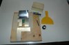
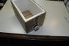
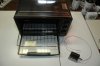
The website was well made and I was able to get an instant quote by filling in the required text boxes. The reasonable prices I received encouraged me to place an order. I was also able to request that a stencil be made and shipped to me together with the PCBs. After a preliminary audit of my Gerber files, I was instructed to send payment by PayPal. Since I did not have a PayPal account it took me several days to get my Visa card tied in to PayPal service. After that, the payment went through and my order was on its way to me. I tracked it on DHL using the number supplied. I was expecting a lengthy delivery. Surprisingly, the shipment arrived 3 days later. I immediately used the stencil and applied solder paste to 2 boards and placed the components. I heated the boards in a toaster oven until a meat thermometer reached the required temperature and the solder visibly melted all around the component leads. The circuit boards worked without any problems and I was able to publish the project quickly.

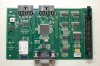
My overall impression of the boards was that they were well made with silkscreen on both sides. I went for the gold immersion option and that made the soldering so much easier. The shipment with the stencil was well protected in hard pressboard so that it would not bend. Shipping time was exceptional considering the distance involved. They assigned a personal contact to me so that I could communicate any issues in English.

Conclusion

I intend to continue to use PVBWay for all my future designs.


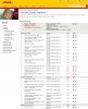
Attached is the shipping track:
 

Attachments

  • DHL.JPG
    DHL.JPG
    213.2 KB · Views: 391
Shipping from China has been very rapid recently without the custom delays that were common a few months ago.

I ordered several boards from Elecrow a few weeks ago on a Tuesday. I had the boards in my hand the next Tuesday! I did opt for DHL shipping, which isn't unreasonable if you're ordering a few boards or a board and other components.
 
Someone please explain to me this soldering in the oven trick. Sounds useful, what is the process to make it work well? How do you add the solder paste? That part sounds tricky.
 
The technique for soldering a board that is designed for surface mounted components is the same for DIY prototypes as it is for production companies that specialize in that field, except that they use more sophisticated equipment.

The CAD system used for laying out the board must have the capability to create Gerber files of various layers. One of those layers is called Solder Paste. This Gerber file is used to guide a laser cutter that creates a stencil made of aluminum foil. The stencil has holes in all the right places where the solder should go on the printed circuit board. In a production environment, the stencil foil will be placed in an aluminum frame and the assembly is hinged so that PCBs can be inserted and removed very quickly. But in a DIY situation, the frame can be omitted and the aluminum foil can be trimmed so that only a couple of inches of foil surrounds the active hole pattern. The foil is taped down to a working surface so that it can be lifted from one end. Place your PCB under the stencil and align it precisely with the pads. Squeeze a line of solder paste on the stencil as wide as the hole pattern. Using a piece of plastic with one straight edge, squeegee the solder paste across the hole pattern. The solder paste will go through the holes and adhere to the pads of the PCB. Lift the stencil gently and remove the PCB. The components now have to be installed one by one using a pair of tweezers. This is the most critical part of the operation since any jarring or a breath of air may move the components off their pads. Usually the solder paste clings to the components and keeps them in place as long as the board is not disturbed to any great extent. The next step is to place the board into an old toaster oven. To get a more accurate reading of the temperature, I use a digital meat thermometer that has a stainless steel probe. I place the probe inside the toaster oven close to where the PCB is sitting. I also put a small dab of solder paste on a piece of old PCB material and position it inside the oven right at the window so that I can see it from the outside. I turn on the oven both top and bottom heaters and watch the temperature come up. As the temperature increases, the solder paste flux begins to boil off. Consult your solder paste product to find out at what temperature the solder will become liquid. Wait until the temperature exceeds this figure by about 20 to 30 degrees C. Verify that the solder has melted by observing the test strip at the oven window. Now turn off the oven and let it cool. The solder should congeal. Make sure you don’t disturb the oven while the solder is melted. When the board has completely cooled, you can install the through-hole components and solder each pin to the board. That’s all there is to it.
 
Very Cool Val, sounds similar to reflow. Not sure I have the steady hands to make that work but very clever indeed.
 
Very Cool Val, sounds similar to reflow. Not sure I have the steady hands to make that work but very clever indeed.

Exactly, it's a homebrew reflow solution. I bought a $15 toaster oven from Walmart (back when I still shopped there) and I use it for soldering all of my surface mount boards. Crank the temperature up to around 400F and let it sit for 3-6 minutes (until the solder visibly flows and components settle). Then shut it off and open the door (You usually want it to cool as fast as possible). Then you're done.

I used this method for my ProtoPIC board. I don't have a photo of the fully-assembled board with me, but here's an Altium 3D model and a photo of the bare board (with a quarter for reference):

6 - PCB_3D_Side.png
10428485_976966252315273_181745044245019007_n.jpg

(I misjudged the size of the silkscreen lettering, so it's a bit difficult to read :p )
 
Here are a few pictures of my rig.
DSC_3340.jpg - a right angle notch in a piece of aluminum the same thickness as a PCB is helpful for inserting boards without having to align each time.
DSC_3345.jpg - for large boards I drill holes in the wooden work surface and place the whole assembly on top of a cardboard box. I insert my central vacuum cleaner hose into the fixture. The vacuum suction helps to hold down the stencil so that there is no solder paste bleed around the edges of the holes. Be sure to reduce the vacuum pressure from the hose. I had my first box crushed beyond repair by a high vacuum setting.
DSC_3346.jpg - the toaster oven with the steak thermometer attached. This an old "Salton Convectaire" with a convection fan in it that helps distribute the hot air more evenly throughout the oven. I attached the thermometer probe with bare copper wire.
 

Attachments

  • DSC_3340.JPG
    DSC_3340.JPG
    432.1 KB · Views: 375
  • DSC_3345.JPG
    DSC_3345.JPG
    433.1 KB · Views: 385
  • DSC_3346.JPG
    DSC_3346.JPG
    348.8 KB · Views: 369
I am gonna have to try this as I have been stressing over soldering some 64 pin TQFP parts. The solder station I would need would bankrupt me I think. Even with my reading glasses I can't see the pins very well. Thanks for sharing this cool method.
 
Nice image Der, that Altium sure makes nice work, you make me jealous. I just can't part with the $7k start price on that package...
 
Val, it would be cool if you could write a instruction book on this method, post it in article section, I am sure it would be a popular read.
 
There is not enough readership here to warrant the effort of writing an article on this subject. Do-It-Yourself electronics aficionados have been performing this method for decades. Just type into Google search box "toaster oven for surface mounted component soldering" and you will get at least a dozen articles. The YouTube video is especially informative.
 
There is not enough readership here to warrant the effort of writing an article on this subject. Do-It-Yourself electronics aficionados have been performing this method for decades. Just type into Google search box "toaster oven for surface mounted component soldering" and you will get at least a dozen articles. The YouTube video is especially informative.

You could even shorten the search to "toaster oven reflow" and get plenty of hits.
 
Okay I will give that a look thanks? BTW, have you done any TQFP parts using this method?
 
Okay I will give that a look thanks? BTW, have you done any TQFP parts using this method?

I have done QFNs using this method. It is very versatile, and provided you apply the solder paste well, it will work with just about any components.
 
Here is a board I did with QFP80 microcontroller chip. I haven't attempted to do any BGA modules, yet.
 

Attachments

  • DSC_3351.JPG
    DSC_3351.JPG
    453.5 KB · Views: 381
The one thing about using the toaster oven, though, is you can't do through-hole components. Then again, that would be the same if you used a regular reflow oven, I imagine.
 
Wow, Val, that came out really nice.
 
So did you have to modify your toaster to control the temperature?
 
Status
Not open for further replies.

Latest threads

New Articles From Microcontroller Tips

Back
Top