Electro Tech is an online community (with over 170,000 members) who enjoy talking about and building electronic circuits, projects and gadgets. To participate you need to register. Registration is free. Click here to register now.
Welcome to our site! Electro Tech is an online community (with over 170,000 members) who enjoy talking about and building electronic circuits, projects and gadgets. To participate you need to register. Registration is free. Click here to register now.
I need more current from my transformer, so I was wondering... is it possible to just paralleling an extra transformer to achieve the double current? I think the winding direction matters, but how to find it - I have no datasheet of the transformer to locate it in.
They can be paralleled if they are identical transformers.
To determine the output polarity connect one output from each transformer together. Power both transformer inputs and measure the AC voltage between the two remaining outputs. If it's 0V then you can connect them together. If not you must reverse one of them to connect them together.
Make sure you don't reverse the input power leads (mark them in some manner) after determining the correct output polarity since reversing the input will also reverse the output.
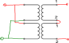
Just to be sure (it very important to avoid something bad happening). I set up the circuit on the figure and measure the output from the primary winding on the second transformer. If the polarity is as shown, I can connect the positive and the negative/ground terminals together.
It's safer if you do the measurement at the secondary as I stated.
You can not measure polarity of a single AC output as shown. The + and - indications on a transformer technically indicate relative phase, (0 or 180 degrees) not polarity.
Now I think I read the text right. If I measure like shown in the figure, the phases will cancel each other to provide a 0 V and I can connect the '1's and '2's together.
Now you have it. If you measure zero AC volts (<1V) between the two outputs, then you can connect them together. If not reverse one of the transformer outputs or inputs.
If your final result is going to a bridge rectifier, it is safer (and may be more convenient) to put each winding into its own bridge and parallel the DC outputs.
I have tried to do the test. Firstly if measured the double voltage of 56V, which should be 0V, so I changed the wires, but the circuit shorted. I don't know what went wrong.
With the other configuration (2x bridges) the outputs can easily be connected to each other and I don't even have to do a special transformer connection.
I have tried to do the test. Firstly if measured the double voltage of 56V, which should be 0V, so I changed the wires, but the circuit shorted. I don't know what went wrong.
I connected the 230V mains to both transformers, and interconnected one wire on each transformer. The last remaining wires (one from each transformer) was used to measure the open circuit voltage.
But strange enough, the circuit shorted and activated the safety circuit.
Here is a quick Eagle schem I whipped up showing the dual-rectifier method (which was also recommended to me over trying to parallel the actual toroids): **broken link removed**
I will do the paralling after the bridges and possible also the filter capacitors (they can then have a smaller voltage rating also). BTW two output wires are just yellow, so no messing up there, but I think it's because it's a special toroidal. It was made to fit several Danish mains years ago (220V, 230V and 240V, so it has several primary wires to make the configuration fit)
I don't know if winging the connections to a transformer is a good idea. If you are working with AC you need a good multimeter bare min. An oscilloscope is actually a must. Things can go very bad really quick.
I don't know if winging the connections to a transformer is a good idea. If you are working with AC you need a good multimeter bare min. An oscilloscope is actually a must. Things can go very bad really quick.
1) The guy hung around here until 2016 (so it didn't blow up and end his time on earth)
2) the guy didn't come back to this thread to complain about bad advice
Conclusion: either the advice he received worked, or he stopped working on the project and never tested the suggestion.
.
.
This site uses cookies to help personalise content, tailor your experience and to keep you logged in if you register.
By continuing to use this site, you are consenting to our use of cookies.
")
