Menticol
Active Member
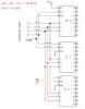
Ok I have made a diagram, I hope its correct
**broken link removed**
The thing consists of a parallel port, 74LS139, a "X" circuit for each 74LS139 output, and its respective relay.
The "X" circuit and relay should change its state when receiving the pulse from the 74LS139, and keep it while the 74LS139 actuates other "X" circuits
If I try to use the schematic without the "x" circuit, I'll be able to turn on only 1 device at time, so would be a controller with limited utility
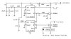
Last edited:
")

 but you still get the idea