Continue to Site

Welcome to our site!

Electro Tech is an online community (with over 170,000 members) who enjoy talking about and building electronic circuits, projects and gadgets. To participate you need to register. Registration is free. Click here to register now.

  • Welcome to our site! Electro Tech is an online community (with over 170,000 members) who enjoy talking about and building electronic circuits, projects and gadgets. To participate you need to register. Registration is free. Click here to register now.

Paper / Credit Card Shredder Fault

Status
Not open for further replies.

spike47

Member
Hi
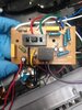
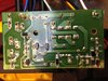
Have a problem with a Shredder, when switched on I put a sheet of paper into the shredder and nothing happens, but if I leave the paper in after a couple of seconds I can hear a buzzing sound coming from the relay then shortly after that the Shredder starts to work .
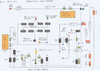
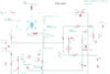
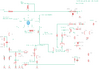
Will post pics and a drawing I have done ( not 100% sure it is correct !) any help on how to test it.

PS: Just a bit more info checked the voltage across the relay when switched on with paper in the slot and got a reading of around 8v , then it started to build up to around 15.8 v then the relay kicked in and it started , prob would of gone up to 24v if left meter on after it started ! .

cheers
Spike
 

Attachments

  • IMG-1259.JPG
    IMG-1259.JPG
    1 MB · Views: 341
  • Shredder PCB.jpg
    Shredder PCB.jpg
    2 MB · Views: 313
  • Shredder V14 flipped wrote on V1 .jpg
    Shredder V14 flipped wrote on V1 .jpg
    3.1 MB · Views: 276
How old is this device? Since C6 is in serial to the relay I would assume that there is something wrong with one or multiple capacitors. The relay will only close (turn on) when C6 is fully loaded according your schematic. I would watch the voltage if its slowly raises and if the relay closes after a certain amount of voltage depending on the relay specifications. If its the case I would change/renew all 3 electrolytic capacitors and try my luck.

-simpleGuy (Trainee)

Hi
Thanks for your reply, yes I was thinking that me be the case, will now do that and see if that works , not sure how old it is , it is my Fathers , it will prob be more on the old than the new .
Just a quickie , does the yellow caps have anything to do with powering the relay or is it just the 3 E caps, and also I can't figure out how the 240v "L" feed gets fed to the PCB , it goes onto the PCB but then it is fed to the Motor from there, can't see it being fed to anywhere else on the PCB !.

Cheers and thanks again for your feedback.

Spike
 
Hi, no the yellow ones are probably for sieving and smoothing the AC voltage. Electrolytic capacitors especially those black ones break down easily after a few years.
If I change capacitors I mostly use Polymer-Aluminium Electrolytic capacitors, they are more reliable. But you can use the exact same ones just new. Will work also
 
How old is this device? Since C6 is in serial to the relay I would assume that there is something wrong with one or multiple capacitors. The relay will only close (turn on) when C6 is fully loaded according your schematic. I would watch the voltage if its slowly raises and if the relay closes after a certain amount of voltage depending on the relay specifications. If its the case I would change/renew all 3 electrolytic capacitors and try my luck.

-simpleGuy (Trainee)

Hi
Changed all the Caps, no luck and it does not even switch on after awhile like before, have done a better schematic .
am thinking of trying to bypass the ir circuit on the board and make up a seperate ir proximiter circuit to feed direct to the 24v relay on board !, need a schematic for it first though, there is plenty of room inside the Shredder .
cheers
Spike
 

Attachments

  • Amazon Paper Shreader 27.11.20a.jpg
    Amazon Paper Shreader 27.11.20a.jpg
    260.9 KB · Views: 245
Hi
Am at work at the moment, the shredder works fine in reverse and works fine if I bypass the relay ! the ir diode is not lit also, that is what feeds the photoelectric diode ! .

ps: attached a revised Schematic
cheers
Spike
 

Attachments

  • Amazon Paper Shreader 06.12.20 v2.png
    Amazon Paper Shreader 06.12.20 v2.png
    24.2 KB · Views: 212
Should D6 be reversed? (I don't see how the transistor gets a base voltage to turn it on).
The relay coil is shown shorted.
 
Should D6 be reversed? (I don't see how the transistor gets a base voltage to turn it on).
The relay coil is shown shorted.

Hi
Thanks for your feedback, yes you are correct had it wrong we round , sorry for the confusion .

pp: attached revised Schematic .
cheers
Spike
 

Attachments

  • Amazon Paper Shredder 08.12.20 v3.png
    Amazon Paper Shredder 08.12.20 v3.png
    24.2 KB · Views: 384
Your diagram is confusing with the use of GND symbols connected to an AC line.

Are you sure the supply to the IR emitter is obtained from the live feed via a motor winding?

Do you have a photodiode or LDR? You have used the symbol of an LDR.
 
Last edited:
Hi
Thanks for your feedback, this is my first attempt to draw a schematic using AutoDesk Eagle, the ground symbols are meant to be the “Neutral” I don’t know what other symbol to use, yes the live feed to the board is through the motor winding .
Yes it is a Photodiode, that was the only symbol I could find in the Eagle library.
Cheers
Spike
 
No problem. With the shreedder off and unplugged, have you tested the transistor and diodes using the diode function on a multimeter?
 
D6 can still not be a Z-Diode but nevermind. Can you put your multimeter to diode/beep mode and check the C -> E and E -> C pins on the transistor (while no power!)? If it beeps, then the transistor is probably broken, to be 100% sure you have to solder it out then check again the C and E pins. A good transistor should be something like X Mega ohm between C and E, only when it gets the base volt & base current (turned on) it becomes almost 0 ohm.

Cheers,
sG

Yes sorry D6 should not of had the Zener symbol next to it, will change drawing to show that, tks.
 
Status
Not open for further replies.

Latest threads

Back
Top