DanManTezz
New Member
Hi everyone,
I have a CDA HVN91FR induction hob that partly works.
2 hobs (connected to one PCB board) are not working. The other 3 are.
Can't see any visual damage/problems.
Upon closer inspection, the power supplied to the rectifier in the 'dead' PCB seems too high.
In the working PCB board (for 2 other working hobs), the power supplied to the rectifier is 100V AC.
In the 'dead' one it's showing 230V AC.
It must be a simple voltage divider somewhere in the circuit but I can't figure it out!
HELP!
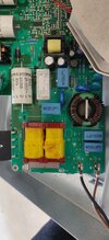
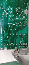
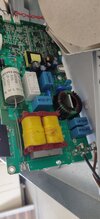
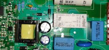
(Images attached of front and back of board; in same orientation)
Power supply on the right, rectifier on left
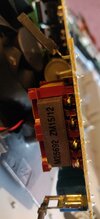
What is the yellow part?
I have a CDA HVN91FR induction hob that partly works.
2 hobs (connected to one PCB board) are not working. The other 3 are.
Can't see any visual damage/problems.
Upon closer inspection, the power supplied to the rectifier in the 'dead' PCB seems too high.
In the working PCB board (for 2 other working hobs), the power supplied to the rectifier is 100V AC.
In the 'dead' one it's showing 230V AC.
It must be a simple voltage divider somewhere in the circuit but I can't figure it out!
HELP!
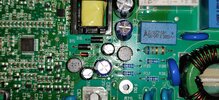
(Images attached of front and back of board; in same orientation)
Power supply on the right, rectifier on left
What is the yellow part?