Continue to Site

Welcome to our site!

Electro Tech is an online community (with over 170,000 members) who enjoy talking about and building electronic circuits, projects and gadgets. To participate you need to register. Registration is free. Click here to register now.

  • Welcome to our site! Electro Tech is an online community (with over 170,000 members) who enjoy talking about and building electronic circuits, projects and gadgets. To participate you need to register. Registration is free. Click here to register now.

OTL headphone amp

Status
Not open for further replies.

ian mason

New Member
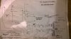
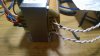
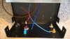
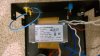
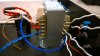
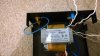
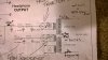
Hello all, I wonder if you might help me, I am currently building a headphone amp that arrived in kit form but I am struggling with the primary wires for the transformer, there are two windings( all white wires) one cable on each winding has black tape on it and one does not, so two wires in total have black tape and two don't, please could someone explain to me in the simplest(but thorough) terms possible how the transformer should be wired according to the schematic for UK 240V, ie the bottom wire goes to the switch and the 2nd wire goes to live on the 3 pin plug(this is an example and probably not how it goes) etc etc, I'm
sorry to act like such a newbie but that's exactly what I am, I would be grateful for any help offered and would like to say thanks in advance.
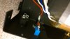
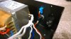
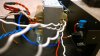
Pictures of the transformer, schematic and plug, switch and fuse are attached.
 

Attachments

  • WP_20171123_020.jpg
    WP_20171123_020.jpg
    742.6 KB · Views: 144
  • WP_20171118_004.jpg
    WP_20171118_004.jpg
    1.4 MB · Views: 126
  • WP_20171120_009.jpg
    WP_20171120_009.jpg
    1.3 MB · Views: 135
  • WP_20171123_007.jpg
    WP_20171123_007.jpg
    697.2 KB · Views: 129
  • WP_20171123_008.jpg
    WP_20171123_008.jpg
    1.3 MB · Views: 112
  • WP_20171123_009.jpg
    WP_20171123_009.jpg
    1.4 MB · Views: 118
  • WP_20171123_010.jpg
    WP_20171123_010.jpg
    1.5 MB · Views: 119
  • WP_20171123_011.jpg
    WP_20171123_011.jpg
    1.4 MB · Views: 118
  • WP_20171123_015.jpg
    WP_20171123_015.jpg
    717.9 KB · Views: 128
  • WP_20171123_016.jpg
    WP_20171123_016.jpg
    752.5 KB · Views: 136
The tape usually indicates the start of the winding, ie which end of the wire was affixed to the bobbin first during the transformer winding process.

When connecting the transformer for a 240v supply, the two primary windings must be connected in series.
The phasing of the two windings is very important, the correct way works fine, the wrong way lets out the magic smoke*.

The correct way to connect the windings is to connect the taped end of one winding to the untaped end of the other winding.

You will then have a taped end and an untapped end to connect to the switch/fuse etc of the incoming mains supply, as per the schematic diagram.

Looking at the schematic, you will see that the primary windings of the transformer have been (ambiguously) annotated with big black dots.
When correctly drawn, the dots should be adjacent to the wire (not on the wire), the dots indicate the start of the winding.

I hope that this clears your confusion.

JimB


* All electronics works using magic smoke.
When the magic smoke comes out, the electronics stop working.:eek:
 
You can using a 1.5v battery and a magnetic compass verify the windings phasing by briefly connecting the battery & observing said compass.
 
Last edited:
You can using a 1.5v battery and a magnetic compass verify the windings phasing by briefly connecting the battery & observing said compass.
Nice trick. I think I knew this a looooong time ago and forgot it.

ak
 
Last edited:
You can using a 1.5v battery and a magnetic compass verify the windings phasing by briefly connecting the battery & observing said compass.
Yes, an interesting trick.
I have never heard of that one before.

Just one criticism, you say to observe the compass, but do not tell us what we should see for correct and incorrect phasing.
I, and many others here know the answer, but the OP and similar inexperienced readers probably do not.
Would you care to expand your description a bit?

JimB
 
For two isolated primary windings as in this thread:
Place compass near the transformer
Connect battery to one winding
Notice the direction of needle movement
Arbitrarily mark one of the primary wires with respect to a battery terminal. For example, mark the wire connected to the + terminal with a piece of tape.
Connect the battery to the other winding
Notice the direction of needle movement
If it is different from before, reverse the battery connections
Mark the wire connected to the + terminal with a piece of tape
You now have the same coil end or winding phase marked for each winding

ak
 
OK, but I had a slightly different way of doing it.

Place the compass on the transformer.
Connect the two windings together.
Connect the battery to the windings,
if the compass needle moves the phasing is correct,
if the compass needle does not move, the phasing is incorrect.

When the phasing is correct, the magnetic fields from each winding add together.
When the phasing is incorrect, the magnetic fields will cancel.

The thought also occurs to me that this will work for both series connections for 240v and parallel connections for 120v.

JimB
 
Quite right Jim, I didnt bother explaining any further as I really didnt expect the Op to go ahead and do the check.

Pretty much all has been said already, test each winding individually.
Torroids dont really work but EI ones usually do unless they are in a full metal can, North and south are top & bottom of the trans, looking at the pic the Op posted the 'pole' end of the trans is where the label is, you'd point the compass north at this, if the north side of the pointer aligns its a south and vice versa, you basically want both marked up windings to make the pointer point the same way with the same polarity.
Some trans you might need a 9v battery if the winding resistance is high, such as a speaker o/p trans for a tube radio.
I use the term briefly check as effectively you are magnetizing the trans using a battery, that might cause fuse blowing issues on power on due to remanence.
 
The transformer images shows a label which proudly boasts: "Quality made in xxxxxxxx".
The xxxxxxx I cannot read or understand from the attached photos. Can you kindly provide?

My rant here is that a transformer intended for a DIY kit should be unambiguously labeled.

This is not a pedantic rant....because of the reasons explained by JimB, the incorrect wiring connections will create a big, across-the-line short.
If the fuse is installed correctly, the problem will stop there, but why subject a newbie to unpleasant surprises and perhaps damage to his kit?
 
Last edited:
I would like to thank you all for your posts and excellent help, I have managed to visit a very knowledgeable gentleman who
fitted the transformer for me and taught me some things about electronics but thanks to everyone for all of your posts.
 
Status
Not open for further replies.

Latest threads

New Articles From Microcontroller Tips

Back
Top