Electro Tech is an online community (with over 170,000 members) who enjoy talking about and building electronic circuits, projects and gadgets. To participate you need to register. Registration is free. Click here to register now.
Welcome to our site! Electro Tech is an online community (with over 170,000 members) who enjoy talking about and building electronic circuits, projects and gadgets. To participate you need to register. Registration is free. Click here to register now.
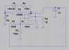
It's a conventional inverting Schmitt-trigger oscillator. R1,2,3 set the bias point for the non-inverting input of op-amp U1. When the inverting input is below the bias point, U1 output is high, which means the bias point is raised above half the supply voltage and defines an upper threshold. U1 output charges C1 via R5 until the inverting input voltage goes above the threshold. This causes U1 output to go low, so R1,2,3 now set a lower threshold and C1 discharges into U1 output, via R4 and R5 in parallel, towards the lower threshold. When that is reached, U1 output goes high again and the cycle repeats.
Next time please post a common image file to show the circuit and, why not, the .asc file. Many here do not have LTSpice installed but could be interested in taking a look.
It makes the charge path into C1 different than the discharge path.
Here are two simulations, one with R4=750KΩ, and the other with it not in the circuit (R4=1GΩ). Note that with R4 open, the output is a square wave. With R4=750K, the duty cycle changes (as does the period).
Oscillator is an electronic circuit which produces a periodic electronic signal, sine wave or a square wave. Oscillators convert direct current from a power supply to an alternating current signal. Oscillator widely used in many electronic devices.
This site uses cookies to help personalise content, tailor your experience and to keep you logged in if you register.
By continuing to use this site, you are consenting to our use of cookies.