Hey Guys.
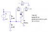
I have a 12V, 0, -12V split power supply as part of my design. Is there any Oscillator chip to work within That voltage? The output must be either sine or Square wave with an accurate 50% duty cycle. The final freq of the Oscillator is 80 kHz to 100 kHz.
Any suggestion please?
Thank.
I have a 12V, 0, -12V split power supply as part of my design. Is there any Oscillator chip to work within That voltage? The output must be either sine or Square wave with an accurate 50% duty cycle. The final freq of the Oscillator is 80 kHz to 100 kHz.
Any suggestion please?
Thank.