Continue to Site

Welcome to our site!

Electro Tech is an online community (with over 170,000 members) who enjoy talking about and building electronic circuits, projects and gadgets. To participate you need to register. Registration is free. Click here to register now.

  • Welcome to our site! Electro Tech is an online community (with over 170,000 members) who enjoy talking about and building electronic circuits, projects and gadgets. To participate you need to register. Registration is free. Click here to register now.

Oscillator

Status
Not open for further replies.
@ contau
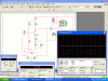
well........ i have already design an RC Phase shift Oscillator. now i wanna learn how to design Colpitts Oscillator. and for that i have already designed a Common emitter Amplifier, i posted that in post number 15. so i wanna know that how can i choose the correct value for OK let's 1MHz. how can i choose values of 2 capacitor and an inductor to make circuit Oscillator at 1MHz? as i told you guys before that i tried many times to design that Tank circuit but i just unable to design the Tank circuit.
In simple word i wanna design a tank circuit for my Amplifier i showed in post number 15 with 1MHz and the Vcc is 9VDc, so the output must be 8V peak. so please help me

Thanks
i have read ur posts.. maybe ur oscilator don't need to use many OPs like that. ofcauze that's just my idea. chosing componets for an oscilator depends on a serveral of factors. i think the best importance of design oscilator is stability of the circuit which relate Q factor directly...
 
@ contau

Brother i read many articles about Tank citcuit but still i am totally unable to design one. so please tell me where i am lacking with some thing or tell some thing i must read before going for designing.


@burhanmz
Hey burhanmz! i asked you that how did you designed your tank circuit because i also want to design a colpitts Oscillator. i wanna design the tank circuit for the Amplifier i designed and shown in post 15. please Help me and tell the way to design the Tank circuit or tell me the way. when i tried to design the tank circuit, i read somewhere that the reactance of the coil of colpitts Oscillator should be around 300Ω and the reactance of the capacitor and inductor should be same at resonance frequency. so using these points i have tried but got no result so i am asking you that tell me what rules you followed to design the tank circuit. please help me.


Thanks
 
Last edited:
1) Pick your frequency
2) find a suitable inductor with high Q at that frequency, remembe that inductor Q rises with frequency, and is givein by: QL = 2*pi*f*L/R, where R is the effective resistance of the inductor (parasitic resistance)
3) After choosing L, use the equation F=1/2*pi*√((C1 + C2)*L), and rearrange to:

C1 + C1=(1/2*pi*F)²*1/L, to get a value of C1+C1

4) Use the above equation, and C2/C1 > 1/Av, where Av is the voltage gain of the transistor amplifier. Allow a little margin to account for resistive losses.

5) Iterate through the procedure and adjust C and L values to get a reasonable value for L, which makes QL large, but keeps the physical size of the inductor reasonable.

6)Simulate your design at each iteration, using the equation in step 2 to calculate a value of R to connect in series with the inductor. The trick here is to allow the sim to run long enough so that oscillations get started. Just keep experimenting.

7)Once you're happy with your values, and the simulation is producing correct results, then build and test your design.
 
Last edited:
Hey! Thanks BrownOut. now i am just starting doing this experiment and will get back to you for what i get the result.
 
Hey! i am just on the R. how to estimate this inductive reactance. this was one of the problem i was facing. as i told before that i read somewhere that the reactance of the coil should be 300Ω at resonance frequency. so i was assuming this and designing my circuit. now what do you suggest me to do? also in the formula in point "2" you told, are we assuming the L to be known?

Thanks
 
Last edited:
hey! bro, i know. i think you did not understand what i ask. i asked that to find both the Q and L, we must know or assume one to find other. right.? so how can i do that.? and to find inductive reactance we or we'll assume it.?or we are gonna assume the value of R?
 
Last edited:
Q is typically specified in the datahsheet. If you just have some inductors lying around, you'll need to measure Q, but that requires some pretty expensive gear. Best to just look over inexpensive inductors in Digi-Key or another discount supplier.
 
But for that formula for inductive Reluctance we need L(Inductance), which we do NOT have.
and please i did not got your last post. Q is specified on datasheet of what.?
 
I've given you everything you need. You need to read it over and put in some effort to understand. Sorry, I'm not going to go over and over and over it...
 
also note you that Q factor (not QL) is calculated overall oscilator circuit, so bias resisters and gm of transitor affect to Q. you should understand and know how to converse serial to parallel vive versa . maybe u r newbi anh i am too but i say the things i knew
 
Hey! Guys I have designed my own colpitts Oscillator. please have a look at it. i have 2 Questions that:

1- How can i improve its sine wave? (like it's clipping from the edges).should i decrease the gain of the Amplifier? if change the gain, then condition for Oscillation goes false and whole Oscillation stops.i have tried changing the value of C3. first i increase it and then decrease it but the only effect was on amplitude, the wave as it is shown(no effect on wave).What should i do now.?

2- Is it possible to increase its Amplitude still more?(what i think is that, we cannot increase the amplitude, but I'm just confirming).
 

Attachments

  • colpitts Oscilla&#116.GIF
    colpitts Oscilla&#116.GIF
    69.9 KB · Views: 135
1) Reduce the gain. It looks like the number of samples needs increasing on the simulator.

2) No, if anything the gain reeds reducing which will reduce the amplitude. A class C amplifier can be used to increase the ampliude.
 
Remvoing C4 would reduce the gain and clean things up a little. What is the scale on the scope? The signal should swing pretty close to the rail before flattening out. What are the maximun and minimum swings? I can't tell from the picture.
 
@ BrownOut

hey! removing C4, reducing the gain so much causing the oscillation to stop that's why instead o f removing the c4 i increased the value of R5 a bit got somewhat more stable sine wave.

And i have show the scale and every thing in pic.
i am using channel A, which is shown 2V/Div.
 
Ah! I see the scale now. In that case, it looks like a sampling problem, as Hero suggested. You can get more output by making R1 bigger and R3 smaller. That raises the base voltage of your transistor, and allow for larger swings. Go to far, however, and you'll cause your transistor to go into saturation at the top of the signal, and you don't want that.
 
Status
Not open for further replies.

Latest threads

New Articles From Microcontroller Tips

Back
Top