Continue to Site

Welcome to our site!

Electro Tech is an online community (with over 170,000 members) who enjoy talking about and building electronic circuits, projects and gadgets. To participate you need to register. Registration is free. Click here to register now.

  • Welcome to our site! Electro Tech is an online community (with over 170,000 members) who enjoy talking about and building electronic circuits, projects and gadgets. To participate you need to register. Registration is free. Click here to register now.

Oscillator

Status
Not open for further replies.

burhanmz

Member
hello

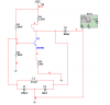
how can i amplify the output with out changing the tank circuit.
lets say i 5v peak to peak at output.
this is colpitts ocsillator so Av=C1/C2 =10/6
just enough to start the oscillations..
fr is around 5kz..
decreasing Re changes sine to somewht u shaped .

is there any way to amplify it without using another amplifier
 

Attachments

  • 1.PNG
    1.PNG
    18.5 KB · Views: 299
Making R2 larger WRT R1 changes the operating point, and thus the output level of the oscillator. Take care when you do this, cause you have a DC feedback path from the amp's collector. You might want to capacitively couple the tuned circuit to the base.
 
Q1 is improperly biased, almost in saturation. Put a capacitor (100nF) between the collector and the tank.
 
putting capacitor from emitter to ground distorts the oscillations and slows down the oscillations to start..
i tried putting capacitor between the tank and base input but that didn't help me with my problem.. i need to control the amplification..
i'll re-bias it and get back to u.
 
Leave in the cap between the tank and base. You're gonna need that to keep the bias correct. Maintain VC above VB always. Show us the levels in the transistor's collector and base when you run the sim. If you want 5V P-P, then your output signal will swing between 9V and 4V. So, you have between 4V and about .7V for the base swing. Since your gain is ~2, then the base will need to swing 2.5V, so try to bias so it swings say, 3.2v - .7V, which requires the base bias to be around 1.95V.


If it stops oscillating, increase the ratio of RC to RE, or add the emitter cap (with a series resistor to avoid distortion). You're running right on the edge of minimum gain.
 
Last edited:
i tried putting capacitor between the tank and base input but that didn't help me with my problem.. i need to control the amplification..
i'll re-bias it and get back to u.
Are you building the circuit, or simulating? In simulation (LTspice), my change (the cap in series with the tank) caused a 5.5V pk-pk output, because the 39k/18k base bias was almost centered.
You should be aware that many oscillator designs don't start unless you introduce a disturbance, as they assume that all components are noise-free and that the power was always there. I start my oscillator simulations by defining the power supply as "PULSE 0 9 0 1u".
 
yes of course i am simulating.. i never thought about the noise free components..
and u say u did get 5.5v pk-pk? i'll test it practically now .. but i reverted to bc337, b/c i was getting distorted sine with 2n3904 in simulation.
 
I got 5.5V pk-pk. The only change I made was to add the capacitor. I just tested it again with BC337-25 and BC337-40. With all 3 devices, the oscillations appear to be about the same amplitude, and the second harmonic 30db below the fundamental.

Which spice are you using?
 
You're using the wrong type of oscillator for kHz. Whilst it is possible to use an LC oscillator at this frequency, it's much more cost effective to use a phase shift oscillator because large inductors are more expensive than resistors and capacitors.

You should also use standard component values: no one sells 60nF capacitors and even if you can buy them from somewhere they'll be more expensive than a standard value such as 68nF.
 
thank u all.. but i did get the biasing corrected and didn't capacitatively couple Re, so that Av=Rc/(re +Re) which gave me the gain condition slightly more than inverse of attenuation that perfectly led start up conditions for the oscillations.
i got 5.7Vpp at 5047hz.
i was kind of using standard values of capacitor.. 60nF can be achieved from paralleling a 10nF with 2 series connected 100nF.

now i'll try the phase shift oscillator.
 
@ burhanmz
Hey! i've also tried colpitts oscillator as per the theory but never got the Oscillation but today i saw your circuit and i am just astonished that how your circuit is Oscillating when you have a gain of 2.2 and i think it is not satisfying the condition for oscillation? well....... even your circuit is working. Well done. so, i must be missing some point. so please help me. I am attaching my Amplifier,please see it. I have designed me Common Emitter Amplifier and tested that is giving me about 10 of the gain. i am having problem designing the Tank circuit. actually in how to choose the correct value of these 2 capacitors and an Inductor.

i read some where that the Impedance of capacitor and inductor should be same at Resonance frequency. using that point, i designed the tank circuit but got not result at all. i have done many Experiments with many different aspects but still i am simply unable to gate the sine wave. so please help me.

Thanks
 

Attachments

  • Common Emitter A&#109.gif
    Common Emitter A&#109.gif
    21.2 KB · Views: 202
Last edited:
@ burhanmz
Hey! i've also tried colpitts oscillator as per the theory but never got the Oscillation but today i saw your circuit and i am just astonished that how your circuit is Oscillating when you have a gain of 2.2 and i think it is not satisfying the condition for oscillation? well.......

Why are you astonished? The gain only need to make up the losses of the feedback network, which is dominated by the capacitor ratio of C2 & C1, ie

60/100 = .6. When mutiplied by the gain of 2.2, the result need to be greater than unity:

2.2 * .6 = 1.32 < 1. More gain would result in more distortion.
 
Last edited:
@Brownout
well.... i understand that now.
@burhanmz
let we have to design in for 10KHz Frequency. i know this type of is not for frequency in KHz but this is tutorial for me so let's design it. so let's design the tank circuit for 10KHz frequency and the input to the circuit is 9VDC so i must wait for an output to come up this atleast 8V peak.i am totally unable to design the tank circuit. so please tell me the way to design the tank circuit for 10KHz of frequency for the circuit i posted in last post.
Thanks
 
Last edited:
for low freqs , maybe u should use the op-am and RC circuit becauz inductor has "big size"....
 
Last edited:
@ contau
well........ i have already design an RC Phase shift Oscillator. now i wanna learn how to design Colpitts Oscillator. and for that i have already designed a Common emitter Amplifier, i posted that in post number 15. so i wanna know that how can i choose the correct value for OK let's 1MHz. how can i choose values of 2 capacitor and an inductor to make circuit Oscillator at 1MHz? as i told you guys before that i tried many times to design that Tank circuit but i just unable to design the Tank circuit.
In simple word i wanna design a tank circuit for my Amplifier i showed in post number 15 with 1MHz and the Vcc is 9VDc, so the output must be 8V peak. so please help me

Thanks
 
Status
Not open for further replies.

Latest threads

New Articles From Microcontroller Tips

Back
Top