Continue to Site

Welcome to our site!

Electro Tech is an online community (with over 170,000 members) who enjoy talking about and building electronic circuits, projects and gadgets. To participate you need to register. Registration is free. Click here to register now.

  • Welcome to our site! Electro Tech is an online community (with over 170,000 members) who enjoy talking about and building electronic circuits, projects and gadgets. To participate you need to register. Registration is free. Click here to register now.

Opto coupler biasing

Status
Not open for further replies.

Suraj143

Active Member
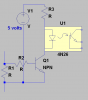
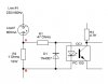
I'm sensing AC current in a Live wire of a load.The load takes 800mA.

What I want is I need to trigger the optocoupler when the load reaches 800mA.

According to V=IR the voltage across A & B is 0.8V which too low to operate opto.

Any simple modifications?

Thanks
 

Attachments

  • Opto Biasing.JPG
    Opto Biasing.JPG
    17.3 KB · Views: 210
Hi,

To start, you'd have to raise the value of the 1 ohm sense resistor so that more voltage can reach the LED of the opto coupler. How accurate this is going to be is questionable however.

Alternately you could try to bias the LED from the mains line with a larger value resistor so that it does not take much voltage across the 1 ohm resistor to turn the LED on and activate the opto. This wont be too accurate either because the line voltage could vary as well as the LED voltage for turn on. We could probably estimate the accuracy if you want to think about doing this.

There's also no hysteresis in those two circuits so the opto would turn on and off with the input line voltage. Better rectification would help here.

So if you dont need too much accuracy either of those above might work ok, but if you need more accuracy you have to go to a comparator type circuit with voltage reference. This kind of circuit can be pretty accurate and can be powered from the mains without losing isolation.
 
Do you have any source of low voltage power where your current sense resistor is? If you had 5 to 12 volts this would really help.
 
Hi thanks for the input.

I cannot understand your 2nd method "bias the LED from the mains line".Can you bit tell how to do this :)

I don't need accuracy.Just to know when the load reaches 800mA. It can be 750mA or 850mA it doesn't matter.

I won't go above 1R resister because the load varies between 0A to 5A.If I use larger resisters it will generate lots of heat.
 
This will turn on at 0.6 volts.
Has some problems but will get you started.
 

Attachments

  • current.png
    current.png
    10.2 KB · Views: 208
You could increase the resistance of the series resistor and then protect the led within the opto with a diode string.
 
R2
If the led has a vf of 2.1v then if you had 4 diodes in series across it the max voltage would be 2.4, and if you put these before R1 you'll have reasonable protection for the led.
 
Optos LED work from 1V to 1.2V.

You are mentioning ronsimpsons circuit?I still didn't get what you mean.
 
Hello again,

By "biasing the LED" i mean you connect a large value resistor from the mains right to the opto LED. That partially increases the voltage so that when the normal sense resistor voltage increases it can exceed the LED voltage and turn it on and hence turn on the opto.
So say the LED turns on at 2v. If it was biased to 1.5v, then when the current goes through the sense resistor (1 ohm) the voltage generated there pushes the LED voltage up higher above 2v and turns it on. As i said though it's not that accurate either.

I like Ron's idea too though. If you can spare a transistor you should get decent operation with that fix. However, beware that you must also derive the +5v supply from the *mains* voltage NOT from the circuit or else you'll loose your isolation which i assume you wanted because of the opto being there in the first place. So you need to build a little power supply (diode, filter cap, etc.) for powering the LED, and it should get it's source voltage from the mains supply, unless of course you dont really need isolation.

In any of these solutions you should also be aware that the opto will pulse on and off unless you filter the input or output.

Hi MrAL I like your idea & Rons Idea.It doesn't need to be accurate.

Here I have drawn what you mentioned.Is this what you mean?
 

Attachments

  • AC sense discrete.JPG
    AC sense discrete.JPG
    18.4 KB · Views: 188
Last edited:
Guys I finally planned to use an opamp & share the same power supply no isolation required.This uses a new low value resistor.Note that I need to power this from single supply not from dual supply.

Here is the circuit. Modifications are welcome.

In LT spice the transistor will bias when the B E voltage reaches 7.8V..!! not when 0.6V
 

Attachments

  • Opamp with current.PNG
    Opamp with current.PNG
    43.4 KB · Views: 166
Simulation of that circuit shows that the transistor doesn't switch at all :confused:
 
Suraj,

There is something fundamentally wrong with your original statement of your problem. If you are trying to sense the presence or absence of 800mA 50Hz AC in a 230V line-powered circuit, then why do you care what the voltage drop across the sensing resistor is???? Presumably, the source of the input voltage is the 230V line, so you must have a series circuit consisting of the line source, your mysterious "load" (which seems to have something to do with a gas-discharge device), and finally a "current sensing" resistor.

You are quibbling about a voltage drop of ~1 to 3V out of 230Vrms (325V peak)? Even if the voltage drop across the sensing element was 3V peak, that is still less than 1% of the applied voltage.

Please post a complete schematic/description of the input circuit you are trying to sense.
 
Last edited:
Here is my suggestion:

I am able to detect <800mA p-p (blue trace) through your mysterious load with only 522mW of loss (purple trace) and 1.8V drop (green trace) in the sensing network. The final output is V(out) light-blue trace.

Note how I modeled the isolation between the line side and the output side...

Works for -50C to +50C, too.
 

Attachments

  • DF92.jpg
    DF92.jpg
    351.4 KB · Views: 174
Last edited:
Another question that occurred to me after I posted above:

Are you trying to produce a logic output that is True if your load current is greater than 800mA and a False if your load current is 799mA? 700mA? 500mA? 1mA?

In other words, how narrow a decision band do you need?

Here is a DC sweep of my posted circuit showing V(out) as a function of sensed current at -25degC (green), 0degC (red), 25degC(lt, blue) and 50degC(blue). I fear that my circuit is too sensitive?
 

Attachments

  • DF92b.jpg
    DF92b.jpg
    243.9 KB · Views: 165
Last edited:
Status
Not open for further replies.

Latest threads

Back
Top