Continue to Site

Welcome to our site!

Electro Tech is an online community (with over 170,000 members) who enjoy talking about and building electronic circuits, projects and gadgets. To participate you need to register. Registration is free. Click here to register now.

  • Welcome to our site! Electro Tech is an online community (with over 170,000 members) who enjoy talking about and building electronic circuits, projects and gadgets. To participate you need to register. Registration is free. Click here to register now.

Accurate mains zero cross detection circuit without optocouplers

Status
Not open for further replies.

Flyback

Well-Known Member
Hi,
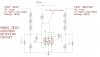
We need an accurate mains zero crossing detector, but cannot use "wear-out" components such as opto-couplers. Do you agree that the attached circuit will be very good?, since it uses matched transistors, and also has Base_collector diodes to sweep out the minority carriers quickly.
The micro will be able to calculate the point of zero cross from the signal from the NPN collectors.
 

Attachments

  • ZCD.JPG
    ZCD.JPG
    162.2 KB · Views: 214
Assuming the frequency is constant, if you time the width it will vary depending on the input being 120VAC (longer) vs. 240VAC (shorter) or some other voltage.
Frequency of course will also determine width, so it might be beneficial in your application to measure the period AND width
 
Every time I see "zero cross" I wonder how precise (time wise) you could be, when real life mains is such a noisy reality.
 
Keep it simple, the old application note AN236 from Microchip shows how a simple resistor and an input pin on a PIC can be your zero-cross detector (with a little math to back-calculate (one time) how long before a detected low-to-high transition into the GPIO that the actual ZX took place.

100FF06E-A5E3-4086-A6FC-7B2FC69610B6.jpeg
 
You can use an RS422 or RS485 style balanced line receiver with an appropriate resistive divider on each input to keep the voltage at the input pins to around +/- 5V max.
(eg. The feeds you have from your bridge rec inputs).

That gives you a true zero crossing at the instant the polarity changes, or rather within a few tens of nanoseconds for a typical 10Mbit rated device.

You can also use a fast comparator, but then you need an extra resistor at each input to bias them within the common mode range. Most line receivers can take something outside the supply range and still work properly.

eg. This one is pretty typical, it can take from -7 to +12 while working on a 5V supply.
**broken link removed**
Data:
 
Status
Not open for further replies.

Latest threads

New Articles From Microcontroller Tips

Back
Top