Continue to Site

Welcome to our site!

Electro Tech is an online community (with over 170,000 members) who enjoy talking about and building electronic circuits, projects and gadgets. To participate you need to register. Registration is free. Click here to register now.

  • Welcome to our site! Electro Tech is an online community (with over 170,000 members) who enjoy talking about and building electronic circuits, projects and gadgets. To participate you need to register. Registration is free. Click here to register now.

Opamp - comparator

Status
Not open for further replies.

kinarfi

Well-Known Member
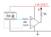
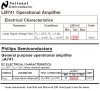
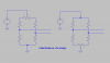
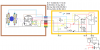
If you have a slowly increasing voltage that is fed to the + of a comparator and an Opamp and a steady voltage fed to the - of each, which will switch first, if either, and at what voltage level. I assume the output holds as each his 0.000 difference, but at what difference do they switch, milli volts, micro volts, nano volts. What would be the correct term to use and is it in the spec sheets, I didn't see it.
Thanks,
Kinarfi
 
Depends primarily on the "input offset voltage" of each. Most common parts have input offsets of mV.
 
hi K,
On very slowly changing input voltage levels to a comparator its essential that you consider adding hysteresis to the comparator.
This is usually achieved by adding low level positive feedback from output to +Vinput.
 
what difference do they switch, milli volts, micro volts, nano volts.

Typical gains can be in the tens of thousands. So, the difference for switching would be 1/gain ~= a hundred microvolt or less. But to be clear, the comparator would ( typically ) switch "faster" as it is optimised for this application.
 
Last edited:
Typical gains can be in the tens of thousands.
Very few opamps have a gain so low. The low power TL06x had a typical DC voltage gain of only 6000.

The lousy old 741 and LM358 opamps have a typical DC voltage gain of 200,000 and better opamps have a gain of 1 million.
 
Thank you, I appreciate you inputs. I have 4 strain gauges and I am hoping to use an Op-amp or a Comparator driving an LED to tell me when I have the balanced or real close + or - about 10 uv, that's about what I can do with my Fluke. The attached drawing should work for either, shouldn't it?
Thanks,
Kinarfi
 

Attachments

  • Untitled.png
    Untitled.png
    4.2 KB · Views: 208
The 20Ks are not needed. You should break the bottom of the bridge and insert a 50Ω balancing trimpot. You should also feed the bridge from a clean, regulated reference voltage, much less than 14V. The 14V will cause self-heating of the bridge.
 
Last edited:
When the inputs of the opamp reach anywhere near balance then the output will slam against both rails, oscillating and/or amplifying the noise. You need to add some hysteresis (positive feedback) to prevent it.
 
Very few opamps have a gain so low. The low power TL06x had a typical DC voltage gain of only 6000.

The lousy old 741 and LM358 opamps have a typical DC voltage gain of 200,000 and better opamps have a gain of 1 million.

200,000 for the lousy old 741 was a marketing fantasy. More realistic was around 20,000.
 
200,000 for the lousy old 741 was a marketing fantasy. More realistic was around 20,000.
But all the manufacturers say the typical voltage gain is 200,000.
 

Attachments

  • 741 voltage gain.PNG
    741 voltage gain.PNG
    42.1 KB · Views: 179
But all the manufacturers say the typical voltage gain is 200,000.

"Typical" gain is a marketing invention. More realistic is what they guarentee. But I know you already know that.
 
Last edited:
I wish semiconductor manufacturers would throw away the bad ones instead of calling them "minimum spec".
Nobody wants one that has a voltage gain 1/10th as much as most.

Maybe product manufacturers buy all the good ones and leave the low gain ones for us hobbiests.

Or maybe semiconductor manufacturers sometimes have a bad yield so all of them have low gain?
 
What I was trying to figure out is, is there enough change in voltage from the strain gauges to work with an opamp or comparator. Turns out there is not enough of a change and in actual use I have an INA128 instrument amp being fed by the bridge. As best as I can see, the change in voltage out is in the 10s of µvolts up to about 2 millivolts. What I'm trying to figure out now is what value of pot will give me the most accurate adjustment for balancing the bridge. What I'm finding with a 5K 25 turn pot is a turn of > 5 degrees will change the output a few hundred µvolts and I want to be with in few 10s of µvolts of 0.000000. I can read .01 mv on my Fluke. I will try a 10K 25 turn pot tomorrow.
Kinarfi
 

Attachments

  • Untitled.png
    Untitled.png
    11.3 KB · Views: 177
  • Untitled.png
    Untitled.png
    24 KB · Views: 169
Last edited:
This is how I have initially balanced a strain gauge bridge.

And I notice you ignored my suggestion to run the bridge on a much lower voltage, preferably regulated.

Here is a good discussion of strain gauges.
 

Attachments

  • IB.png
    IB.png
    11.1 KB · Views: 198
Last edited:
hi K,
I use the same method as MikeM has posted for nulling a bridge.

A 5K balancing pot is much too higher value, even for a 20 turn pot, try a 10R or 100R.

If you are using a following A2D converter, many are ratiometeric, so ideally you should power the bridge with the same regulated supply as the ADC.
Its also possible with some IA/A2D's to null out any offset voltage due to small gauge imbalance.

Also for a nominal 350R bridge the supply voltage is too high, try 5V, you want to avoid self heating of the gauge elements.
 
To balance my bridge, which of these would you recommend and why? I prefer the last of the three because I believe it would have the least effect, a 10Ω 21 turn pot is the smallest with the most turns I have been able to find and I will probably end up with middle example. My measurement show that the bridge is unbalanced by one leg having .1Ω more than the others, but my INA128 is multiplying it's effect by about 1000. Another idea I have is to parallel the pot in example 1 with a 1Ω resistor. I haven't tried it yet, do you think it would give finer adjustments?
If I stayed with the 14 volt excitation, I would end up with each half of the bridge developing 280 milliwatts of heat, it's recommended to stay under 100, so using 8 volts will yield 92 milliwatts of heat. Because I am trying to keep things working in the mid range of 14 volts, I plan to float the regulated 8 volts on a 2.4 v zener. Your advise and comments are very much appreciated.
Thank You,
Kinarfi
 

Attachments

  • 1Untitled.png
    1Untitled.png
    54.1 KB · Views: 169
  • Untitled.png
    Untitled.png
    25.3 KB · Views: 164
  • Untitled.png
    Untitled.png
    32.5 KB · Views: 173
Last edited:
To balance my bridge, which of these would you recommend and why? I prefer the last of the three because I believe it would have the least effect, a 10Ω 21 turn pot is the smallest with the most turns I have been able to find and I will probably end up with middle example. My measurement show that the bridge is unbalanced by one leg having .1Ω more than the others, but my INA128 is multiplying it's effect by about 1000. Another idea I have is to parallel the pot in example 1 with a 1Ω resistor. I haven't tried it yet, do you think it would give finer adjustments?
If I stayed with the 14 volt excitation, I would end up with each half of the bridge developing 280 milliwatts of heat, it's recommended to stay under 100, so using 8 volts will yield 92 milliwatts of heat. Because I am trying to keep things working in the mid range of 14 volts, I plan to float the regulated 8 volts on a 2.4 v zener. Your advise and comments are very much appreciated.
Thank You,
Kinarfi

hi,
I would use fig 1 [a], a 10Rpot in the top of the bridge, ends of the pot to the gauges.

Floating the bridges 8Vext on top a Zener is a bad idea, a zener voltage is not stable enough.

Why do you need to have a floating system with a mid range of 14V.?

Can you post your full circuit diagram.
 
Eric, Here's the full schematic with some circles added for description purposes and a rough description of the theory of operation.
The main body has been in service and works quite well.
The top 2 boxes are changes I'm working on, the brown box is mounted on / to the steering shaft, the yellow box will be mounted to the frame and is for adjustments
most of the rest is in it's own box mounted to the frame.
The red circle is the triangle oscillator for the design.
The blue circle mixes the oscillator with ''fixed" voltages above and below the mid point voltage.
Note: My thoughts are that even though the vehicle voltage varies, 12-14.4 volts, every thing varies proportionally so the relationship of wave forms used remains relatively constant.
The green circle, comparator, responds to the inputs from the yellow box and the fixed wave forms to drive the H bridge.
The relay is for shut down, triggered by end of travel (EOT), pink circle, or over current, grey circles.
The bridge drive is set up so the PFET are on or off and are turned on slightly before the NFETS which are PWM according the how far the control voltage varies from the mid point.
Because PFETs can't handle the current an NFET can and NFETs use + voltage to the gate, the NFET nearest the battery is for turning the circuit on and off via the Key by opening the ground path.
Made a few minor corrections and addition of components.
 

Attachments

  • Rev-7.05 Eric .png
    Rev-7.05 Eric .png
    165.2 KB · Views: 164
  • Rev-7.05 - 8 +2.4 VOLT.png
    Rev-7.05 - 8 +2.4 VOLT.png
    102.5 KB · Views: 175
Last edited:
hi,
I have copied the text and the png, see if I can come up with an idea.
 
It should be noted that I made an error in my description, the bridge PFETs are on when there is no torque which provides dynamic brake to stop bump steering and hold the steering in it's last position and then turned off prior to the NFET being turned on
 
Status
Not open for further replies.

Latest threads

Back
Top