Continue to Site

Welcome to our site!

Electro Tech is an online community (with over 170,000 members) who enjoy talking about and building electronic circuits, projects and gadgets. To participate you need to register. Registration is free. Click here to register now.

  • Welcome to our site! Electro Tech is an online community (with over 170,000 members) who enjoy talking about and building electronic circuits, projects and gadgets. To participate you need to register. Registration is free. Click here to register now.

op amp design

Status
Not open for further replies.

prescott2006

New Member
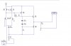
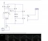
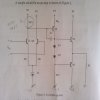
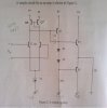
i am designing an opamp to obtain open lop gain of 4000.i arrive at the second one.can somebody provide me the real circuit to replace the current source?and can you show me the connection to measure open loop gain?

circuit source: Ron H from allaboutcircuits.com
 

Attachments

  • DSC00860.jpg
    DSC00860.jpg
    31.4 KB · Views: 329
  • op amp with higher gain.JPG
    op amp with higher gain.JPG
    25.3 KB · Views: 314
Last edited:
The output of your first stage should be connected to Q7/Q2. For the current, look up "current mirror." That method only works well as an integrated circuit, or you can find a matching transistor pair.
 
i connect like this to measure open loop gain ,is it correct?but i only manage get gain of 100 (7/0.0707).can you help me check whether the circuit is correct or not?
 

Attachments

  • urt.jpg
    urt.jpg
    49.5 KB · Views: 225
Your test method totally won't work. Your operating voltage is not applied correctly. Also, there seems to be a connection missing betweeen Q7 and Q5.
 
Last edited:
You negative -15V power supply is wrongly shown as a positive +15V supply.
 
sorry,my bad.there really got connection.i simulate it and get such value.29.16m/7.07u=4124,so the circuit is correct for gain 4000?
 

Attachments

  • check.jpg
    check.jpg
    91.9 KB · Views: 203
It only works through the "magic" of simulation. This would never work in a real circuit.
 
First, connect the operating voltage correctly. Look over this discussion to learn how. The simulation works, but in the real world, a 10uV source doesn't exist. Use the link I provided to see how to do this correctly. If this is just an exercise in "theoritical" imaginary electronics, you're probably done.
 
ok,then refer to your attachment.i just need to connect the same connection into my circuit?the value of the resistor also same?
 
why i measure the v out is -1.2m while vx is 475 m.the v out not suppose to be larger than the vx?

circuit source: Ron H from allaboutcircuits.com
 

Attachments

  • simple discrete op amp.asc
    4 KB · Views: 150
Last edited:
CONNECT VEE CORRECTLY!!!!

As you continue to refuse to correct this problem, you'll never get anything to work.
 
Last edited:
i really not sure why my vee got problem.it is connected to -15v.i am really a beginner,maybe i cannot follow your meaning,can you modify the circuit for me?
 
Status
Not open for further replies.

Latest threads

New Articles From Microcontroller Tips

Back
Top