Continue to Site

Welcome to our site!

Electro Tech is an online community (with over 170,000 members) who enjoy talking about and building electronic circuits, projects and gadgets. To participate you need to register. Registration is free. Click here to register now.

  • Welcome to our site! Electro Tech is an online community (with over 170,000 members) who enjoy talking about and building electronic circuits, projects and gadgets. To participate you need to register. Registration is free. Click here to register now.

op amp comparator circuit

Status
Not open for further replies.

MrDEB

Well-Known Member
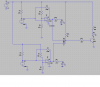
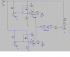
working on a comparator circuit which measures two different voltages on two seperate op amps then using a NAND gate , if both op amp outputs are same then output drives LED (going to be a 400 ohm relay)
 
forgot pic

oups got to quick
it works in LT spice
 

Attachments

  • temp control.PNG
    temp control.PNG
    34.8 KB · Views: 2,064
How about using two open-collector voltage comparators like **broken link removed**s? Set one up to switch high when it's input is >3V; set the other up to switch high when it's input is >4V. Wire the two outputs together to a common pull-up resistor. The combined output will be high if and only if both comparators are above their respective trip points.
 
Last edited:
That would be too easy

besides I have several LM324's on hand that I want to use.
have similar project using same LM342 (had 20 units given to me)
 
besides I have several LM324's on hand that I want to use.
have similar project using same LM342 (had 20 units given to me)

hi
You could use a couple of diodes and resistor to make an OR gate to replace the logic ic.
 
hi
You could use a couple of diodes and resistor to make an OR gate to replace the logic ic.

Looks like he used two NAND gates to make an AND gate, not a OR gate, both inputs need to be logic 1, or did I miss something?
 
Last edited:
Looks like he used two NAND gates to make an AND gate, not a OR gate, both inputs need to be logic 1, or did I miss something?

Ok, so three diodes then :)
 
Looks like he used two NAND gates to make an AND gate, not a OR gate, both inputs need to be logic 1, or did I miss something?

Two diodes can be used to make either an OR or an AND, whats the problem.?

Why dont you suggest to the OP a way of solving the problem rather than nit picking my humble submission.:rolleyes:
 
Ok, so three diodes then :)

hi Deb

Please post your LTS asc file and I will add diodes as required.

Confirm the operating sense of the relay drive transistor that you require.:)
 
Sorry Eric, no offense to you, you did say or gate. Not to negate your input. My apologies. :)
 
Sorry Eric, no offense to you, you did say or gate. Not to negate your input. My apologies. :)

consider this.:)
IF the OP had wanted the relay to denenergise when either of the comp outputs had gone low then it would be an OR gate.
 
I was under the assumption that both inputs must be true, else relay is off. Actually after re-reading OP I wonder if he wants XOR function? I did not mean to offend, often forum communication creates misinterpretation.
 
I was under the assumption that both inputs must be true, else relay is off. Actually after re-reading OP I wonder if he wants XOR function? I did not mean to offend, often forum communication creates misinterpretation.

Why do you think you are offending me.:)

Like you I dont not know for sure what the OP wants to do.:rolleyes:
I assumed that the mention of two diodes would start bells ringing in MrDebs head, as a possible solution.
 
Last edited:
both op amp outputs high

in order for relay to energize
hope I got this right??
 

Attachments

  • temp control2..PNG
    temp control2..PNG
    33.2 KB · Views: 820
Why do you think you are offending me.:)

Like you I dont not know for sure what the OP wants to do.:rolleyes:
I assumed that the mention of two diodes would start bells ringing in MrDebs head, as a possible solution.

In the end, your solution seems to be good one, was not trying to jab you, ya know I luv ya man. :)
 
another project

it works in simulation
 

Attachments

  • battery monitor2.asc
    2.9 KB · Views: 155
it works in simulation

hi,
Look at these two modified asc.

When is the battery monitor supposed to switch on/out.?
 

Attachments

  • AAesp03.gif
    AAesp03.gif
    32.9 KB · Views: 205
  • AAesp04.gif
    AAesp04.gif
    28.6 KB · Views: 197
  • battery monitor2(3).asc
    3 KB · Views: 143
  • temp control.asc
    4.3 KB · Views: 152
Last edited:
Status
Not open for further replies.

Latest threads

New Articles From Microcontroller Tips

Back
Top