Wow, Dana! That circuit sure brings back memories, like when I was an airman serving in the U.S. Air Force between May 1963 and May 1967. IIRC, someone published this, or a similar circuit, in Popular Electronics magazine. At my permanent duty station we had a "bench stock" supply of NE-51 bayonet-base neon indicator lamps.
These lamps NEVER burned out, but they would darken with age and usage, eventually becoming so dim as to be useless as indicator lamps. Hence, the bench stock supply existed to allow the timely replacement of "burned out" or blackened lamps that were no longer useful. Our squadron had a huge bench stock of components that someone thought would be useful for flight-line maintenance with no need for paperwork to order the parts.
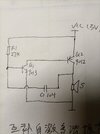
The circuit can be extended indefinitely to multiple neon lamps that flicker on in succession by connecting C2 (output) to the next neon lamp and increasing the C2 value from 0.01 uF to 0.1 uF.
One of the guys in my squadron of Armament and Electronics (A&E) technicians built the circuit using about a dozen NE-51 lamps, mounted in random locations on a small piece of polycarbonate clear plastic. The flickering display of seemingly "randomly distributed" lamps, sequentially illuminating, was visually impressive. Other airmen saw his display and several of them (not me) decided to emulate it with NE-51 lamps taken from bench stock. The big problem was the battery required to operate the display. Not only were these NOT stocked as bench stock, but they were expensive. The "makers" of these novelty neon lamp displays tried several approaches to obtaining the voltage necessary to "fire" a neon lamp, but the simplest approach was to use line voltage and a silicon half-wave rectifier plus a small-valued "smoothing" capacitor.
Nobody realized how dangerous this AC line-operation actually was. After all, we all worked in and around airplanes (B-52H bombers) carrying thermonuclear weapons, with at least half of the fleet always armed and on standby alert, and the other half armed and flying "airborne alert." At our young ages we were afraid of nothing. And no one who made one of these neon lamp displays was in the least bit concerned that they were stealing the neon lamps to make a toy. Because the bench stock was only inventoried to replace parts removed from bench stock, and any parts removed from bench stock were never accounted for, they felt pretty safe that the theft would either (1) not be discovered or (2) was such a trivial amount that no one would care. I never did find out if anyone was caught or punished for "misappropriation of Government property."
Hop -- AC8NS