Continue to Site

Welcome to our site!

Electro Tech is an online community (with over 170,000 members) who enjoy talking about and building electronic circuits, projects and gadgets. To participate you need to register. Registration is free. Click here to register now.

  • Welcome to our site! Electro Tech is an online community (with over 170,000 members) who enjoy talking about and building electronic circuits, projects and gadgets. To participate you need to register. Registration is free. Click here to register now.

on complementary multivibrator

Status
Not open for further replies.

xljin2006

Member
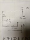
this is complementary multivibrator.

here is what I can understand: at first,vcc goes through r1,c1,s,to charge c1 . when c1 left voltage goes to about 0.5v, q1 starts to conduct. and that makes q2 to conduct. and collector voltage of q2 goes high. this is coupled to base of Q1 by c1. this is positive feedback.

my question: what will happen next?how vibrator works?
 

Attachments

  • IMG_20230514_194647.jpg
    IMG_20230514_194647.jpg
    2.6 MB · Views: 240
Solution
adding those resistors switched the polarity of it!!!!
The output pulses to the load (or speaker) are still very short positive spikes.
Also, check the labels at the top of each image, the colour are not necessarily the same from one to the other.

The part about the motor makes no sense, sorry??
That is a really old circuit that produces "Geiger counter" style clicks. It's a relaxation oscillator, not actually a multivibrator.

It's not a nice circuit; when the transistors turn on, it's effectively shorting Q2 base-emitter across the power supply... It does work, but I'd suggest only running it from smallish batteries that cannot supply high currents, to avoid cooking the transistors.

Connect eg. a 1M pot in series with R1, to be able to slow down the clicks.


This is the sequence:
C1 charges via R1 until Q1 starts to conduct, That in turn causes Q2 to conduct, and it's collector (the speaker upper terminal) is pulled positive.

That makes the right hand end of C1 positive, and that then has to charge in the opposite direction, via the base of Q1, "locking" that on until the charge current through C1 drops down enough, then Q1 & Q2 turn off.

That allows the speaker to pull the right side of C1 down to near 0V, and as C1 was last charged right side positive, the left side is now negative of ground.

Then the sequence repeats.
 
That makes the right hand end of C1 positive, and that then has to charge in the opposite direction, via the base of Q1, "locking" that on until the charge current through C1 drops down enough, then Q1 & Q2 turn off.

Then the sequence repeats.

I think voltage of right hand end of c1 goes up doesn't charge C1 to opposite direction. c1 will couple it to base of q1.
 
I think q2 base will be fixed to vcc-0.7v.
It will but the base is also pulled down to ground via the other transistor when it turns ON, so the 'be' junction of Q2 is directly across the battery - BOOM!!!!!. As has been said, a crappy circuit with important components missing.
 
That is a really old circuit that produces "Geiger counter" style clicks. It's a relaxation oscillator, not actually a multivibrator.
It's not a nice circuit;
Yes a pretty horrible attempt at a circuit - presumably a crude and nasty attempt to reduce it to the fewest possible components?,
Guys - show some respect.

That circuit dates back to the late 1950's. It was popular in hobbyist circles because it made a sound with the bare minimum number of parts, especially transistors. In today's money they were $20.00 each.

Kids these days - no sense of history.

ak
 
This is a simulation of the original circuit, operating from a 3V power source that can provide very high current.

Q1 base current peaks at ~30A and Q2 base current peaks at ~40A.

The load current in to the 8 Ohm resistor (representing the speaker) peaks at about 150mA

Q1 base voltage stays around 0.7 - 0.8V, the right hand side of the cap (Q2 collector) swings between 0V and 1.3V

Relaxation_Osc_Original.jpg


Adding a couple of low value resistors to limit the base currents takes the peaks down to more realistic levels, and increases the current through the load to around 300mA peak.

Relaxation_Osc_Mod1.jpg
 
Wow, Dana! That circuit sure brings back memories, like when I was an airman serving in the U.S. Air Force between May 1963 and May 1967. IIRC, someone published this, or a similar circuit, in Popular Electronics magazine. At my permanent duty station we had a "bench stock" supply of NE-51 bayonet-base neon indicator lamps.

These lamps NEVER burned out, but they would darken with age and usage, eventually becoming so dim as to be useless as indicator lamps. Hence, the bench stock supply existed to allow the timely replacement of "burned out" or blackened lamps that were no longer useful. Our squadron had a huge bench stock of components that someone thought would be useful for flight-line maintenance with no need for paperwork to order the parts.

The circuit can be extended indefinitely to multiple neon lamps that flicker on in succession by connecting C2 (output) to the next neon lamp and increasing the C2 value from 0.01 uF to 0.1 uF.

One of the guys in my squadron of Armament and Electronics (A&E) technicians built the circuit using about a dozen NE-51 lamps, mounted in random locations on a small piece of polycarbonate clear plastic. The flickering display of seemingly "randomly distributed" lamps, sequentially illuminating, was visually impressive. Other airmen saw his display and several of them (not me) decided to emulate it with NE-51 lamps taken from bench stock. The big problem was the battery required to operate the display. Not only were these NOT stocked as bench stock, but they were expensive. The "makers" of these novelty neon lamp displays tried several approaches to obtaining the voltage necessary to "fire" a neon lamp, but the simplest approach was to use line voltage and a silicon half-wave rectifier plus a small-valued "smoothing" capacitor.

Nobody realized how dangerous this AC line-operation actually was. After all, we all worked in and around airplanes (B-52H bombers) carrying thermonuclear weapons, with at least half of the fleet always armed and on standby alert, and the other half armed and flying "airborne alert." At our young ages we were afraid of nothing. And no one who made one of these neon lamp displays was in the least bit concerned that they were stealing the neon lamps to make a toy. Because the bench stock was only inventoried to replace parts removed from bench stock, and any parts removed from bench stock were never accounted for, they felt pretty safe that the theft would either (1) not be discovered or (2) was such a trivial amount that no one would care. I never did find out if anyone was caught or punished for "misappropriation of Government property."

Hop -- AC8NS
I remember that magazine issue. It included flip flops and logic made out of NE2's.

Attached .....

Regards, Dana.
 

Attachments

  • GE Neon Lamps 1965.pdf
    77.5 MB · Views: 214
  • Neon glow lamps_ more than simple light sources.pdf
    1.3 MB · Views: 200
  • neon.pdf
    3 MB · Views: 224
  • UsingAndUnderstandingMiniatureNeonLamps.pdf
    2.5 MB · Views: 230
Guys - show some respect.

That circuit dates back to the late 1950's. It was popular in hobbyist circles because it made a sound with the bare minimum number of parts, especially transistors. In today's money they were $20.00 each.

Kids these days - no sense of history.

ak

I can't say I remember it until relatively 'recently', and you couldn't get NPN transistors in the early days. all were germanium PNP devices.

You also wouldn't want to design a circuit that kills your VERY expensive transistors for the cost of a couple (or even one) cheap resistor.
 
Already explained.


When the circuit triggers and both transistors turn on, the right side of the cap is pulled to power while the left cannot vary much from 0.7V, so it very rapidly charges in the opposite direction.

is it charge or discharge?I think it is discharge. the road is: c1 left ---q1 base-emitter---gnd---vcc---q2 emitter-collector---c1 right. but the problem is c1 right hand voltage is high, should it be low? and how?

why should it discharge? why not stay at the transistors turn on state?
 
The transistors do not have enough gain to stay saturated "on" and sustain the current through the 8 Ohm load, with just the 27K providing base current.

It relies in the capacitor reverse charge current to hold it on, once it starts to turn on; as soon as it starts to switch out of saturation & the voltage across the load drop at all, that change is coupled to the first transistor base and both shut off.


To me, "discharge" is reducing to or towards zero voltage, like "stopping" is reducing to zero speed.

Reversing voltage like reversing direction on a motor is charging / accelerating in the opposite direction. It may go through zero but that's not the end state.

Look at the sim of the unmodified circuit:
The blue trace is cap left, the green cap right. The green trace goes both far more positive and far more negative than blue: The cap is charged in both directions / both polarities.
 
Status
Not open for further replies.

Latest threads

New Articles From Microcontroller Tips

Back
Top