Continue to Site

Welcome to our site!

Electro Tech is an online community (with over 170,000 members) who enjoy talking about and building electronic circuits, projects and gadgets. To participate you need to register. Registration is free. Click here to register now.

  • Welcome to our site! Electro Tech is an online community (with over 170,000 members) who enjoy talking about and building electronic circuits, projects and gadgets. To participate you need to register. Registration is free. Click here to register now.

Oatley Electronics K173 Multi-purpose Inverter Kit ADVICE

Status
Not open for further replies.
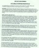
I recently purchased an inverter kit that advertised:

"This modified square wave inverter can be used to convert 12 or 24V DC to 240V AC, 120V AC or any other voltage."

I have constructed only a few projects (555 timer checker, PWM, & battery charger) and am very new (but very interested) to electronics. I can follow instructions pretty well, but when I received this kit, the instructions are for building this inverter to handle 240v mains not 120v. I specifically got this kit as a simple beginning but am completely in the dark as to adjust it to my needs.

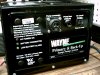
Recently, I was able to buy 4 Interstate 190aH batteries cheap. They are holding a charge and I wish to use them to power my lab or shop. I have found a descent PM motor for use as a generator and eventually I will build my own windmill and alternator. My wife and I are currently seeking to move to Kentucky and find a place out in the sticks where we can live off the grid so I will need to wait to do that. I have a fairly adequate shop so there is much I can make once we get there. Sorry to get off track.

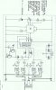
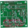
It would be very much appreciated if I could get some help constructing this kit inverter for 24v operation at 110v mains. I would also like to use better MOSFETs as the ones in the kit are substandard to what is printed on the PCB.

This is my first post so I hope the attached information turns out. Thanks for your help and advice in advance.

Tony
 

Attachments

  • OATLEY INVERTER INSTRUCTIONS a.jpg
    OATLEY INVERTER INSTRUCTIONS a.jpg
    200.2 KB · Views: 1,045
  • INVERTER SCHEMATIC a.jpg
    INVERTER SCHEMATIC a.jpg
    84.5 KB · Views: 1,754
  • PCB INVERTER 1.jpg
    PCB INVERTER 1.jpg
    47.4 KB · Views: 7,301
The only difference between 240V and and 120V is the final transformer.
 
I'm I correct in assuming that I don't need to change out the voltage regulator (7808) in order to use 24vdc coming in?

Thanks, Tony

PS: Love your quote! My wife has five!!
 
I wasn't sure if I could still use the 7808, I'm new at this and I appreciate the help. I pulled up the data sheet and it tells me the input voltage is 10.5 to 23 volts but the absolute max rating is 35v? Do you think if I heatsink it with a fan that it would still be trouble?

Thanks, Tony
 
Actually I want to build this inverter as a learning project and a stepping stone to something larger. I've found a few inverter circuits on the net but this kit seemed to be a good beginning. As I mentioned above, I have four huge 190aH batts and eventually would like to use them (in conjunction with wind/solar) to power my lab and shop.
 
Inverters are best left to companies that build them well teamleader, especially for real power output. You're gonna save yourself a lot of time effort and money just determining what your power needs are and buying a commercial unit to meet your needs. There are many other types of circuits you can learn on better, and building your own is almost guaranteed to cost you more than a compareable commercial unit.
 
I know you are correct; I've read many other comments from people who have said the same thing. It just burns me up that I will end up buying a product from China (because it's cheaper) that could be made for a fraction of the price. But... In the mean time I still have a kit that I would like to put together even if I only use it to run a couple of circuits. What I will probably do is build it to operate off of one 12v batt and keep it simple. I have many scavenged transformers and quite a few MOTs I could rewind too. I have already used two of my scavaged MOT to build a welder for my shop (works GREAT off my regular mains power). Your advise is much appreciated!
 
The only thing I would warn you about with that circuit is I don't see any obvious over current control, then again I can barely read the schematic cause it's sideways and my neck already hurts =) So if you hook up something that draws too much current it may kill the Mosfets, so just be aware of what you plug into it.
 
Sorry about the schematic pic. Oatley messed me over on the MOSFETs. They gave me a comparable, but sub-standard kind. I am considering using better MOSFETs and I will keep my eye on the watts I use for this inverter. I could also put a fuse in? This is what Oatley advertised:
With one pair (supplied) of mosfets and no additional heatsinks 100W power output is possible. 200W with two pairs (addtional pair of mosfets an option) of mosfets and no additional heatsinks. 400W and higher with two pairs of mosfets and additional heatsinks
 
Upgrading the components you use certainly will help. And yeah.. a Fuse would be nice =) If you put really good mosfets in there heat may be less of an issue, but I wouldn't push it too far since this isn't something you've done before. When you go to test it try adding 25 watt lightbulbs on a power strip one at a time and wait 5 minutes inbetween each one. Once you get up to four bulbs and it's still running at an acceptable temperature swap it for a 100 watt bulb and gradually increase the load till the measured temperature reaches what you're comfortable with.
 
Also, monitor the voltage as you're adding bulbs. When voltage hits 100-110v, that's pretty much the limit in power. There is no output voltage regulation, so voltage is going to drop with load.

You should also use all your batteries at once. Keeps them in sync with each other.
 
As for the MOSFETs, I've got two 75a 55v UltraFETs I'd like to use? But I need to consider the gate voltage, right? The power strip is a great idea and I will go that route.

I junk picked a sump pumb back-up power supply/battery charger unit last week that I have charging two of my big batteries. The output of the power supply side is 27.5 volts DC. I thought maybe I could use this supply for an inverter.
 

Attachments

  • PICT0271.JPG
    PICT0271.JPG
    781.1 KB · Views: 440
Not the gate voltage, but the gate current. For them to switch fast enough, you're going to have to pump quite a bit into them. May need a driver circuit for each.

Do you have a datasheet for the mostfets?
 
Don't high power inverters tend to use Igfets? So the gate drive isn't such a problem? For a lower power inverter switching losses shouldn't be too much of a concern?
 
If you mean the 7808 then it's going to get mighty hot with a 24v supply.

No its not. Even though there is 16V across the 7808, the current being drawn is very small. The only things that the 7808 is supplying is the 555 and the 4017 counter; 10mA max, so the 7808 is dissipating 160mW. You could use a 78L08 :p
 
I've read as a somewhat general guideline to use IGBTs in 1kw and over. I'm sure there are gives and takes to that, depending on the application.

Those mosfets are big. Although you're switching at a very slow frequency, so I'm not sure what the waveform would look like driving them directly from the ICs. Although there is going to be quite a turn on delay.

The one thing I don't see on the schematic is any pulldown resistors on the gates. Might not be a problem with the small mosfets they gave you, but with the large ones you'll need something to pull the charge from the gate to turn it off. When you start pulling enough current through them, they will eventually self-latch on and fry themselves. Driver ICs are better, but more costly.
 
Last edited:
Problem with pulldown resistors is they decrease switching speed based on the IC's current ability. More Mosftet heat. I was asuming the IC was push/pulling the mosfets.
 
Status
Not open for further replies.

Latest threads

New Articles From Microcontroller Tips

Back
Top