Continue to Site

Welcome to our site!

Electro Tech is an online community (with over 170,000 members) who enjoy talking about and building electronic circuits, projects and gadgets. To participate you need to register. Registration is free. Click here to register now.

  • Welcome to our site! Electro Tech is an online community (with over 170,000 members) who enjoy talking about and building electronic circuits, projects and gadgets. To participate you need to register. Registration is free. Click here to register now.

Oatley Electronics K173 Multi-purpose Inverter Kit ADVICE

Status
Not open for further replies.
If you give me some numbers on the MOSFET's I might be able to find a Datasheet for you!
 
The 7808 will not get hot as it is delivering only about 15mA. Do you have a transformer that is basically 12 - 0 - 12 to 110v?

The circuit is very simple. It is a square wave oscillator with timing that produces a roundish square wave output due to the inductance of the transformer. But the circuit has no feedback and the voltage will fluctuate according to the current drawn.
Most modern inverters have a "sense" line and they drop down to a few milliamp when not being used.
They also have "current sense" to provide a constant output voltage up to about 120% rating.
Your circuit will depend heavily on the VA rating of your transformer.
 
I think I will stick with the small MOSFETs until I know what I'm doing. I do have several 12 - 0 - 12 to 110v tranformers. Would I be able to use 24vdc with this set-up?

The MOSFET datasheets are posted above.

Thanks all!
 
Last edited:
I would have to check that. I have a lot of MOTs and could wind one. I've got #10 wire. Couldn't be too difficult, wrap five turns and measure? Do I need a 24v - 0 - 24v to 100v in order to use 24vdc input?? Thanks
 
You would actually want to wind something like 24v to 140v. They actually state in the plans to use a 9v to 230v transformer. Most likely they are boosting the voltage a bit high to make up for the loss when a load is applied.

And the turn-on times for the those mosfets would be...

dT = Qg / Ig

55v mosfet: 175nC / 5ma = 35us
60v mosfet: 152nC / 5ma = 30.4us

The one thing I just noticed when looking at the 4017 datasheet is that the outputs are sinks when HIGH. That's why they don't need the pulldown resistors on the gates.
 
Last edited:
Firstly, if you deliver 24v to a 12v winding, you will get 240v from the secondary, for the transformer you are using.

Secondly, if you deliver 24v to the 12v winding, you will have to be very careful about the duration of the pulse so that you don't saturate the core.
You can do it (without saturating the core), but you will still get 240v out.
The reason they use the 9v winding is because the voltages ascribed to the transformer are AC. The 9v winding will deliver more than 13v AC and we are using it in reverse to supply 12v DC.
 
Last edited:
I am going to try and work on this transformer situation in reverse. I've got the HV secondary winding from a MOT already removed. I just wrapped 11 turns of #10 wire on it. I am going to run a 6a fuse in series on the primary because I read somewhere that you cannot rewind a single MOT without a load. Supposidly the MOT designers knew that these MOTs would always have a load on them (the magnaton) so they purposely used less primary windings. If I blow the fuse then I'll know they are correct. They recommend using two MOTs in series that is supposed to rectify this problem. I will somehow have to calculate the turns ratio in order to find out the primary output(?). I want to see what voltage I will get out of my secondary side with the 11 turns.

Advice???
 
Make sure you adjust the frequency to 240hz for 60hz output.
 
Why did you buy a kit made in Australia where the voltage is 230VAC?
It is such a simple circuit that its output is a square-wave. Most electronic products do not work properly with a square-wave because they are designed for the sine-wave from the mains that has a peak voltage much higher.
 
The reason I bought this kit was because of the advertisement from Oatley, as follows:
This modified square wave inverter can be used to convert 12 or 24V DC to 240V AC, 120V AC or any other voltage. Power and voltage outputs depend on transformer. Output frequency is adjustable between 50 and 60Hz and a beat indicator circuit is included (LED) so you can easily adjust the frequency to be the same as the mains frequency.
I believed the instructions would show how build the various configurations.
 
The kit didn't come with the transformer. I most likely will rewind a MOT to suite my needs. I have one I'm experimenting with now on the bench.
 
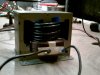
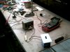
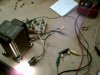
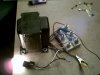
Don't really know, but, I just tried out my rewind, 19 turns on secondary with #10 wire and got only 19.6vac out of it. Hooked up bridge and cap, got 27.7vdc. In my next experiment I will run 24vac into the secondary and see what comes out of the primary. If I have to, I will wind some more turns on the primary, but that will mean I need to take one of my MOTs apart for the wire (which involves grinding, cutting, etc)
 
I know you are using the transformer "in reverse" to what it was originally intended, but the transformer is now a "step-up" transformer and the primary is the 12v winding and the secondary is the 110v winding.
Unless you stick to convention, I don't know what you are doing.

Does the core have E’s and I’s?

What is its VA rating?
 
I am working this tranformer problem in reverse. I cannot even know for sure whether the primary windings on this transformer are normal 115v because I have read that the designers of MOTs purposely used less windings then normal because they knew there would always be a load on them (ie the magatron), so, my next step, that I will attempt in a couple minutes, is to attach a 24vac source to the secondary and see what I'll get out of the primary.

My next move is going through all my transformers with a 24vac test.
 

Attachments

  • MOT 1.JPG
    MOT 1.JPG
    621.1 KB · Views: 296
  • MOT 2.JPG
    MOT 2.JPG
    201.8 KB · Views: 224
I think I may have found a transformer that might work on this project. I've hooked up the secondaries to 24vac and I'm getting 121vac (no load). I observed that my voltage goes down as I progressively use higher wattage bulbs as a load. My highest wattage is a 75 watt 130v bulb and my meter is reading 98vac. I'm not sure what this indicates. Smanches, you said I would probably need an output of 140vac; do you think 121vac will work? The transformer is out of an old television so I'm not sure of how much current it would handle and I really cannot test that with my test ac 24 volt supply. I only want 200 or 300 watts, if I can get it.
 

Attachments

  • PICT0323.JPG
    PICT0323.JPG
    698.1 KB · Views: 325
  • PICT0324.JPG
    PICT0324.JPG
    712.7 KB · Views: 215
Status
Not open for further replies.

New Articles From Microcontroller Tips

Back
Top