Electro Tech is an online community (with over 170,000 members) who enjoy talking about and building electronic circuits, projects and gadgets. To participate you need to register. Registration is free. Click here to register now.
Welcome to our site! Electro Tech is an online community (with over 170,000 members) who enjoy talking about and building electronic circuits, projects and gadgets. To participate you need to register. Registration is free. Click here to register now.
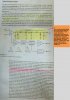
1 Yes it is a correct configuration.
Just consider it as two inductors with very short leads!
2 The two squiggly lines infer that there are several similar circuits like the ones with the tapped inductors, but it is too tedious the draw them all.
I think they did a poor job. The squiggle isn't a symbol, but rather just a simulated break. You might see it used when something is say connected by a cable and it's not close. A dumb example is say you had a fire sensor and a control panel. The sensor connections and the panel would be drawn together, but the double-squiggle lets you know that the sensor is not inside the fire panel. e.g. long connection.
I THINK what they are trying to convey (and doing a very poor job of it) is that stages can be added. A "stage" is the center-tapped inductor and capacitor combination. They could also indicate that this could be a long wire.
I'm using the text that said "multiple stages" and real life to say "long wire". May actually be both.
Bad writing.
Early delay lines were lust a length of cable coiled with a large diameter inside the scope.
I agree with KISS, it is a badly drawn circuit.
You have to know what the circuit looks like to understand the book which is trying to teach what the circuit looks like.
When I wrote my original reply, the thought did occur to me that the squiggle is often used to represent a break in a long line, but "prior knowledge" seduced me into ignoring that possibility here.
Some oscilloscopes use a long cable, effectively a transmission line, as the delay line.
I was thinking that another possibility is they could be drawing those half/half inductors with center capacitors just to represent the distributed inductance and capacitance of an actual transmission line. Thus they could be indicating a transmission line is actually part of the delay line. Not the whole thing, but part of it.
Apparently they did not intend to concentrate too much on the delay line or they would of had to draw it more clearly i think.
These kinds of questions arise sometimes when we try to extract too much information from a drawing (or text) for something that was intended to convey only general information about a topic.
This site uses cookies to help personalise content, tailor your experience and to keep you logged in if you register.
By continuing to use this site, you are consenting to our use of cookies.