Continue to Site

Welcome to our site!

Electro Tech is an online community (with over 170,000 members) who enjoy talking about and building electronic circuits, projects and gadgets. To participate you need to register. Registration is free. Click here to register now.

  • Welcome to our site! Electro Tech is an online community (with over 170,000 members) who enjoy talking about and building electronic circuits, projects and gadgets. To participate you need to register. Registration is free. Click here to register now.

Basic question about capacitors output

Status
Not open for further replies.
I apologize if I've made this post in the wrong section.

I'm having trouble understanding how I can figure amperage output of a capacitor or if that's even the right way to look at the situation.

I've got two very large capacitors and I'm wondering if there's a significant difference in the amount of effective power output of a small (electrolytic) capacitor vs a very large (oil filled film capacitor) one with the same capacitance and voltage ratings.

For example the two capacitors that I've got are 200ųF and 4kV DC, but when I Google a capacitor with these same specs I don't find anything that looks similar in size to these ones that I've got. So what i'd like to know is, if these capacitors are just less prone to burning out than an electrolytic capacitor of the same specs? Or do they just have more storage capacity?

Heres the math ive done so far, I can tell that these things obviously store a tremendous amount of energy and will definitely be lethal.


½ x (0.0002) x (4,000)² = 1,600
^ ^ ^
Farads x Volts = Joules


0.0002 x 4,000 = 0.8
^ ^ ^
Farads x Volts = Coulombs

Why can a smaller capacitor have all these same characteristics?
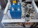
 
Here's a picture of the capacitors I'm talking about
 

Attachments

  • 20220313_192337.jpg
    20220313_192337.jpg
    2.6 MB · Views: 433
To highlight just how deadly those are, a 44 magnum has a muzzle energy of ~1200J. And a defibrillator is ~200J.

Sorry, don't know answer to your question but would guess that the oil has a much higher beakdown voltage.

Mike.
 
The electrolytic capacitor is polarized (can only be charged in one direction), and the film capacitor non-polarized so can be charged by either polarity.
The film capacitor is larger and has lower inductance and ESR, so can be used at higher frequencies with lower loss.
Film capacitors also generally have a longer operating life than electrolytics.
There is otherwise no significant difference in the energy they can store.

What do you mean by the "amperage" of a capacitor?
 
What do you mean by the "amperage" of a capacitor?
Forgive my ignorance. How can I calculate the current this thing is capable of outputting when it discharges at a given voltage?

1,600 Joules @ 4kV would equate to .4 Joules per volt of input. What would the power of the discharge be measured in?
 
16,000 Joules is 16,000 Watt Seconds. If you had a 100% efficient converter to 5V then it could supply 1A for 16,000/5 =3600 seconds or one hour.

Mike.
 
Thank you Mike.

Reason I acquired these is because I'm interested in building a ZVS induction heater.They were also only $50, so I was hoping I could make them work.

I've been reading all I can and watching all the videos on YouTube about induction heater builds to get some kind of idea.

I've got a 30A 40V regulated DC power supply that I could use to charge up the capacitors initially, but that wouldn't be a sufficient source of power to keep the induction heater going would it?

I think the power supply actually uses like 1800W, I cant imagine that would be a sufficient amount of power to maintain the charge in the capacitors.

I was thinking of making a flyback transformer to step the voltage of my power supply up to 4kV to charge the capacitors, but like I said I don't think that it outputs enough power to keep the capacitors charged under a heavy load lile when the induction kiln is running continuously to melt steel.

Would it make more sense to just supply mains and step the voltage up with an isolation transformer, then rectify to DC and use that to charge the capacitors?
 
It sounds like you have very little experience in electronics. If so then playing with 4kV is not recommended. Plus, you don't need high voltage. Why not buy this module from banggood? It runs at 48V and outputs 1kW. They also have smaller units, I suggest getting one and study it to see how it works. The power supply you have sounds suitable to power that module and will be much safer.

Mike.
 
Different physical sizes for the same capacitance & voltage ratings are down to different constructions for different purposes.

The big ones you have a likely paper & oil, or plastic film, dielectric plus fairly heavy foil "plates", so capable of standing extremely high short term currents.

Other constructions like metallised film and/or electrolytic can be much smaller, but have higher internal resistance and not capable of handling current anywhere near as high without heating or damage.

Re. an induction heater:

Those, especially the so-called "ZVS" type [which are not zero voltage switching, just simple and nasty] use a driven "tuned circuit", an inductor and capacitor in parallel.

The currents in that coil and capacitor are massive and can me quite a bit higher than the drive voltage, due to the resonance, so high current rated caps are essential.
However if it's going to run from a practical voltage using conventional transistors, it's still going to be possibly around 100 - 200V as a likely maximum.
 
Could you guys recommend something for me to read so I can have a better underatanding of capacitors?

I've ordered that small induction heater that pommie reccomended so I can get a better idea of what's going on.

I know that with an induction heater i dont want high voltage, I want high frequency of switching. I know I need to read more, I'm not thinking about charging these up anytime soon. I've got no experience with DC so im not messing around with it, but I'd like to get a better understanding.

ve read that that the circuit would need to be "tuned" to the resonant frequency with an oscilloscope.

I had originally asked about "amperage" of a capacitor because that figure is mentioned in the video below.

That same guy has a website where he goes into detail and he keeps talking about amperage of capacitors
 
Last edited:
You need a basic understanding of capacitors. Caps don't use energy, they store it. The energy is used in heating things. Anything that gets hot is using energy. Energy is also stored in Inductors (coils) and when the circuit is tuned the amount of energy in each is the same and it's resonating - the energy is going back and forward between the two. The only place that energy is being used is the resistance of the coil and eddy currents in the item (being heated) in the coil. Look up (google) "LC resonant circuits".

This is my simplistic version of what I think is happening, maybe someone who understands analogue power electronics can better explain it - I'm more a software guy.

Mike.
 
I understand that the function of a capacitor is to store energy, not to use it.

My understanding of capacitors is that the amount of "power" that it can discharge is limited by the amount of Volts you use to charge it up and the capacitance is what determines how much "power" is stored per volt of charge.

By my (probably wrong) calculations one of these capacitors when charged up to its max of 4kV can deliver 16 Joules per second at discharge. 1 second is equal to 1 hertz, and the circuit is going to be switching at a frequency of 100,000 - 200,000 hertz does this mean that the the wattage output per cycle increases proportional to the frequency?

I'm sorry if these are bonehead questions, this stuff is foreign to me. You've been helpful so far Mike and I appreciate it.
 
  • Like
Reactions: jjw
In a parallel LC circuit the Q factor acts on the current in a series LC circuit it increases the voltage. Lookup Inductor Q factor for more info. Therefore the current in the LC circuit can be much higher than the current being supplied. Note that the high current will only heat the inductor (and the Capacitor ESR) through the resistance (very little) so a high current is required. The power feeding the circuit (1000W in the module linked above) is going into inducing eddy currents and therefore heat in any conducting object in the coil and the coil itself. Note, even the one linked above can be dangerous, I've heard stories of people with rings getting them heated up and by the time they realise it's too late and they end up badly burned. A 1000W heater would easily make a gold ring glow red.

If the output is only 500W, a 5g wedding ring if in the coil for 1 second will heat up to ~750°C.

Mike.
 
By my (probably wrong) calculations one of these capacitors when charged up to its max of 4kV can deliver 16 Joules per second at discharge.
It does not work quite like that..

For a rough analogy, think of the capacitor something like a balloon; it can be filled to store energy and that energy released.

The maximum pressure the balloon can stand is equivalent to its maximum voltage limit, before it bursts (the insulation fails).

How much current it can stand is a bit like how big the pipe is that connects the balloon.


For plastic film or pulse-rated capacitors, the charge/discharge limit is generally given as the maximum permissible rate of change of charge level, in volts per microsecond.

The current that rate corresponds to depends on the value of that specific capacitor.
You can work it back from the basic Coulomb equation: A current of one amp causes a voltage change of one volt per second, with a one farad capacitor.

(So eg. in proportion, one amp with a one microfarad cap will cause a voltage change of one volt per microsecond; a millionth the capacitance so a million times faster change).

Example - this capacitor, just because it looks a bit like the ones in your photo...

Look in the data sheet for it:

The entry for that is part way down page 4; It's a 250V rated, 13mm diameter x 31.5mm long body type.

Go back to the reference data table on page 2, and for a 250V rated and 31.5mm body one, the maximum dV/dT is 6V per uS.


For electrolytic capacitors, it's very different.
The maximum "ripple current" rating is given directly, for specific frequencies - but also the life expectancies for electrolytics are stated as very short times, like typically 1000 to 5000 hours; around 40 to 200 days....
Those figures are based on them being run at maximum at all ratings, like voltage, temperature, current etc..

The makers then give calculations for life factor based on how much you under-run the cap - so eg. at half voltage, half ripple current and moderate temperature, the lifetime may be thousands of times longer than the base figure.
 
Status
Not open for further replies.

Latest threads

New Articles From Microcontroller Tips

Back
Top