Continue to Site

Welcome to our site!

Electro Tech is an online community (with over 170,000 members) who enjoy talking about and building electronic circuits, projects and gadgets. To participate you need to register. Registration is free. Click here to register now.

  • Welcome to our site! Electro Tech is an online community (with over 170,000 members) who enjoy talking about and building electronic circuits, projects and gadgets. To participate you need to register. Registration is free. Click here to register now.

NTC Thermistor to turn LED on / off

Status
Not open for further replies.
ikalogic said:
An op-amp and a potentiometer will always give you more accurate results and easier control.
Yes, but I like to follow the KISS school of design. Or as someone so famously said, "Make it a simple as possible, but no simpler".

For this simple On/Off lamp function I think a couple resistors and perhaps a diode or two is all that's needed. If that's shown to not work, only then do you go more complex.

But that's just my philosophy.
 
While I was at radio shack in looking for more resistors and a transistor, I decided to purchase the 500 variety pack. Figure the money spent for those would save me gas money for multiple trips later. Wish I had done this earlier.

I took crutschow advice and just lowered the resistor in series with the LED. I used 1/4 watt resistors.

After about 5 different resistors (lowering ohms), I got the result I've been looking for!

I've had to put two diode's in series with the LED to get it drop when the thermistor is at full resistance. I'll have to get the values of the diode worked out but that's just part of the tweaking.

This KISS method has worked me.

I'll spend the next few days perfecting this method that Crutschow has described.

Crutschow, hat's off to you in getting me through this project. This method is small, compact with very few components.

Thank you!
 
Ok, bad news.

In using the method that crutschow has described, my resistors are heating up.

I'm using 1w resistors.

I'm using a mock up with a 12v power supply at 1amp.

What can I do to cut down on the extreme heat these resistors are putting off? Extreme heat being to hot to touch.
 
osphoto said:
In using the method that crutschow has described, my resistors are heating up.

I'm using 1w resistors.

I'm using a mock up with a 12v power supply at 1amp.

What can I do to cut down on the extreme heat these resistors are putting off? Extreme heat being to hot to touch.
What are the resistor values you're using?
 
Resistors Value
1 Watt @ 200 Ohms
Which is parallel To:
Series: Diod + Diod (12 V rated diods) + LED + 1 watt @ 22 Ohms

This will start to heat up after about 3 to 4 minutes. And it gets hotter the longer I leave the power on.
 
In doing more research, another application is doing something similar to what I'm doing.

They are using a 5W resistor and come to think of it, I didn't ask at what ohm. My guess would be 200ohm.

They also mentioned doing a comparative voltage circuit. This being a manufacture company.

I'll try the 5 Watt before doing a whole circuit design. Maybe that'll keep the heat down.
 
osphoto said:
Resistors Value
1 Watt @ 200 Ohms
Which is parallel To:
Series: Diod + Diod (12 V rated diods) + LED + 1 watt @ 22 Ohms

This will start to heat up after about 3 to 4 minutes. And it gets hotter the longer I leave the power on.
I assume it's just the 200 ohm resistor that's heating up since it would take over 100mA to heat up the 22 ohm resistor and that's a lot of current to be running through the LED which will shorten its life. If it is getting hot you may need to increase its value. You can determine the LED current by measuring the voltage accros the resistor and using ohm's law (I = V/R).

You could use a higher wattage 200 ohm resistor which would reduce the temperature some (but not the power dissipated).

The only way to reduce the power is to increase the value of the 200 ohm resistor. You may then have to add more diodes in series with the LED to keep it off when the thermistor is in liquid.

You could also use one zener diode in place of the regular diodes. Zeners come in various voltages and you just select the voltage you need. Each regular diode has a drop of about 0.65V so you can determine the voltage you need by multiplying the number of diodes needed by 0.65V . The difference is the Zener is reverse biased in normal operation (plus voltage on the cathode).
 
If the 22 ohm resistor is getting hot, you're running too much current through the LED. You should increase it's value.

You can increase the 200 ohm also but that may require adding more diodes to keep the diode off when the thermistor is in liquid. If you prefer, you can just increase the wattage so the resistor runs cooler.

Incidently, resistors normally get hot when dissipating their rated power.
 
So, I can expect to get "REALLY" hot resistors then and thats OK.

I just haven't let the bake enough to see how hot they can really get.

If I go higher then the 22ohms on the LED side, the brightness isn't to its fullest.

I plan to pick up a some resistors rated at 1/2 and I'm gonna see if I can get some 5 watt @ 200 ohms. maybe that'll help with the heat also.

I also need to verify my power source on the actual device that this is going to be used at. Like the Amps.

I'll keep plunking away at this.
 
osphoto said:
I also need to verify my power source on the actual device that this is going to be used at. Like the Amps.
A typical battery voltage when an engine is charging is around 14V so you may want the check your circuit with that voltage.

The current capability of a lead-acid battery is high, since it typically has to supply starter current, which is likely more than 50A. It will generally supply whatever the load requires based upon the load resistance. For a short-circuit, an automotive battery can supply several hundred amps for a short period (makes a cheap welder).
 
Cheap welder? That sounds like a voice of experience.

I wont get a chance to test all this again until later this weekend. Plus I'll need a trip to Fry's for the resistor since Radio Shack doesn't have a 5watt in the 200 ohm size.
 
osphoto said:
Cheap welder? That sounds like a voice of experience.
I wont get a chance to test all this again until later this weekend. Plus I'll need a trip to Fry's for the resistor since Radio Shack doesn't have a 5watt in the 200 ohm size.

hi osphoto,
Following this thread I would have suggested using the 'ikalogic' or the 'boncuk' solution. The project would have now been finished and installed.

The KISS design if taken too far will give you grief, you will have to keep tinkering with the values, until possibly, you get it sort of working.

As 'crutschow' says
"Make it a simple as possible, but no simpler"., which I agree with, but this is NOT the KISS method.

Anyway, I wish you every success...:)

Regards
 
NTC to switch an LED

osphoto said:
I have a NTC Thermistor rating of about : .75 - 1.1k Ohms @ 25C

This thermistor is used in a motorcycle gas tank.

Typically, a 12v lamp is used to indicate the fuel is low, Thermistor is at it's lest resistance.

I want to replace the 12v lamp with and LED. Seems simple enough since my knowledge of using an LED is using the resistor that comes with the LED in line with a power source.

This doesn't work since the thermistor has constant ground backed by 12v's and even at the highest resistance on the thermistor, the LED stays on.

What is the simplest way for me to get this to work?

I just want the LED to come on when there is no gas in the tank and OFF when there is gas in the tank.

Thank you in advanced.

I'm not sure what other info is needed.


Osphoto:

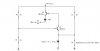
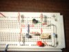
I felt compelled to give you a hand here! I took the liberty of designing; implementing and testing a circuit for you. I have supplied a schematic, and picture of the circuit along with a couple of data sheets. Also below are the circuit voltage measurements, to verify component power consumption. Using a PIC here would have been the first choice-though I assume this is not an option for you.

In your post above you noted that the thermistor is grounded at one end-therefore the circuit reflects this. Also the circuit allows a good ohm range for the LED turn-off (884 -1100 ohms), Vsource=12 volts (actual=11.81 V) and (908 -1100 ohms), Vsource=16 volts (actual=16.46 V). Your bike electrical system falls between these values; which means, when there is no gas in the tank, the LED will begin to turn on, when the thermistor resistance values are below the values stated above. The circuit will work for a Vsource less than 12 volts (vehicle during start, weak battery, etc.), due to the bridge voltage at Vbe1.

The circuit was tested half the time for each case using first a 12 volt, then a 16 volt source, 4 hours with the LED on (no gas in tank), and 4 hours with the LED off (gas in the tank). This was done, to test the circuit endurance and assure reliability. As seen below the results tested fine, no components were hot at any time as expected in the design.

Short circuit description:

The design is a bridge circuit, with the base-emitter diode of Q1 acting as the load, and thermistor resistance (Rt) causing the imbalance. Having the base and emitter of Q1 share the same voltage reference, assures that the critical Vbe1 voltage will change in proportion for an applied varying generated voltage. Q2 was added for a higher LED current/voltage gain since collector current in Q1 is limited by Rt, R1 and R2.

Parts needed:

4-1 Kohm resistors (3 of ¼ watt, and 1 of ½ watt-->LED resistor)
1-2N3904, NPN transistor
1-2N3906, PNP transistor
1-LED, 40 – 80 mW
1-9.1 volt Zener diode (protection only if thermistor open circuited)

Circuit measurements for no gas in tank, LED on (Vsource=12 volts)

NOTE: The values in brackets are the Vsource=16 volt measurements. Also
1 Kohm was used in all calculations with R1, R2, R3 and R4.

Total circuit current=22.2 mA, Total circuit power=266.4 mW (512 mW)

LED current=9.69 mA, LED voltage = 2.0 V, LED power = 19.4 mW < 80 mW (29.4 mW). With Vsource=16 V the LED will consume a maximum power of 30 mW.

Vce1=5.78 V, Ic1=0.45 mA, PQ1=2.6 mW << 625 mW (9.43 mW)

Vbe1=0.664 V (0.664 V)

Vebo= 5.89 V (thermistor open cicuit and w/o Zener) < 6.0 V

Vebo=3.215 V (thermistor open circuit and with Zener) < 6.0 (0.941V)

Vebo= 7.50 V (Vsource=16 V, thermistor open cicuit and w/o Zener)
> 6.0 V, thus reason for the Zener

Vce2=0.062 V, Ic2=I (LED) =9.69 mA, PQ2=0.6 mW << 500 mW (0.77 mW)

VR1=5.87 V, Power R1=34.5 mW < 250 mW (66.5 mW)

VR2=5.93 V, Power R2=35.2 mW < 250 mW (68.2 mW)

VR3=6.51 V, Power R3=42.4 mW < 250 mW (80 mW)

VR4=V (LED) = 9.74 V, Power R4=94.9 mW < 500 mW (202 mW)

VRt (simulated thermistor voltage, no gas in tank with Rt =750 ohms):
VRt=5.29 V, Power Rt =37.3 mW (76.8 mW)

Rt =thermistor resistance @ LED turn off (gas in tank)=884 ohms (908 ohms) With the bike not running and the ignition switch on, the LED will be off when fuel cools the thermistor between 884-1100 ohms. When the bike is running, this actual value depends on the generated voltage, but will fall somewhere between 884 - 908 ohms.

Zener current= negligible (negligible)

Circuit measurements for gas in tank, LED off (Vsource=12 volts)

Again note that the values in brackets are the Vsource=16 volt measurements.

Total circuit current=11.4 mA, Total circuit power=136.8 mW (254 mW)

VR1=5.88 V, Power R1=34.6 mW < 250 mW (66.9 mW)

VR2=5.93 V, Power R2=35.3 mW < 250 mW (68.4 mW)

VR3=6.51 V, Power R3=31.8 mW < 250 mW (61.3 mW)

VRt (simulated thermistor voltage, gas in tank with Rt =1100 ohms):
VRt=6.19 V, Power Rt =34.8 mW (67.5 mW)

Zener current=0.01 mA (0.01 mA)
 

Attachments

  • Schematic.JPG
    Schematic.JPG
    17.4 KB · Views: 458
  • NTC_Jpeg.JPG
    NTC_Jpeg.JPG
    187.9 KB · Views: 369
  • 2N3904.pdf
    111.3 KB · Views: 293
  • 2N3906.pdf
    57.6 KB · Views: 232
Last edited:
hi second286,

Thats the way to do it.

Nice and simple AND it works...:) :) :)
 
I am trying to do the same thing on with my motorcycle. I have measured the resistance of the thermistor at room temperature and it is around 1.4k ohms. Would Second286's Bridge circuit work with my thermistor as well?
 
You guys are forgetting one fundamental aspect of this seemingly simple circuit. The original Lamp-Thermistor circuit exhibits a "bistable" behavior due to the non-linear resistance vs current that flows in the lamp. If you take out the lamp, and replace it with an LED, you loose the bistable nature of the circuit, and the LED turn-on will be too gradual to show the tank being empty.

Obviously, you could add some sort of active amplification with positive feedback to achieve what just the lamp and thermistor did all by themselves.
Here is a case where replacing a lamp with a LED just to look cool is a bad idea.
 
Status
Not open for further replies.

Latest threads

Back
Top