Aquamon, I suggest you do some theory proving of your own. Your circuit has some serious drawbacks.
First, your circuit is just a motor reversing circuit. I wouldn't call it an H-bridge, because that usually means that it is being controlled by logic inputs, which yours is not. Yours requires that it be controlled by two external toggle switches or relays; one to turn it on/off (motor run/motor stop), and the other to select the motor direction (requires tying Rev to either the battery voltage, or to ground). Begs the question, if you need toggle switches (or relays) to control the circuit, why bother with the circuit; just control the motor directly from the switches?
Better still,
just use a center-off, Double-Pole, Double-throw toggle switch. Only one switch, zero power wasted.
Second, a quick simulation shows how inefficient your circuit is.
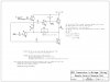
View attachment 90096 View attachment 90097
With Rev tied low, with a 100Ω load, the voltage drop across the upper Darlington is 1.5V and the drop across the bottom one is 0.7V, leaving only 9.8V across the load (motor). With a battery voltage of 12V, that means you wasted 2.2V.
With Rev tied high, with a 100Ω load, the voltage drop across the upper Darlington is 1.9V and the drop across the bottom one is 0.7V, leaving only 9.4V across the load (motor). With a battery voltage of 12V, that means you wasted 2.6V. The difference is due to the additional drop across D1; why is it even there?
As suggested by Audioguru, contrast your motor reversing circuit to the simplicity and performance of what modern PFETS and NFETs can do:
View attachment 90098
Note that with such a light load (100mA), the voltage drop across the both top and bottom devices is a few mV. This circuit could switch several Amps and not break a sweat. Try that with yours...