Trevor Rymell
Member
Dear All
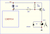
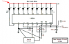
I have a small circuit using an LM3914 to drive a 10-segment LED bar graph. The supply voltage to the circuit is 5 VDC.
If I measure the voltage across any LED when lit I get about 2.3 volts.
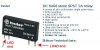
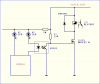
My question is, can I use that 2.3 volts to drive a simple transistor switch that will then turn on a 5 volt relay coil without effecting the LED brightness? I hope I've explained that adequately.
I've looked at sample circuits using a transistor as a switch but haven't succeeded in making it work.
Thanks and regards
Trevor
I have a small circuit using an LM3914 to drive a 10-segment LED bar graph. The supply voltage to the circuit is 5 VDC.
If I measure the voltage across any LED when lit I get about 2.3 volts.
My question is, can I use that 2.3 volts to drive a simple transistor switch that will then turn on a 5 volt relay coil without effecting the LED brightness? I hope I've explained that adequately.
I've looked at sample circuits using a transistor as a switch but haven't succeeded in making it work.
Thanks and regards
Trevor