Continue to Site

Welcome to our site!

Electro Tech is an online community (with over 170,000 members) who enjoy talking about and building electronic circuits, projects and gadgets. To participate you need to register. Registration is free. Click here to register now.

  • Welcome to our site! Electro Tech is an online community (with over 170,000 members) who enjoy talking about and building electronic circuits, projects and gadgets. To participate you need to register. Registration is free. Click here to register now.

NOR gate oscillator in LTspice not working

Status
Not open for further replies.

Flyback

Well-Known Member
Hi,
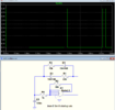
Do you know why the NOR osc attached isnt working?...i think its something to do with race hazard?
 

Attachments

  • NOR oscillator.asc
    1.3 KB · Views: 225
  • NOR osc not work.jpg
    NOR osc not work.jpg
    71.9 KB · Views: 246
Yes, it is sort of a race hazard.
You need to add hysteresis to the circuit.
A relaxation oscillator needs hysteresis for proper operation and your ideal NOR gate has essentially none.
One way to do this, is to add a couple resistors from the input to the non-inverting output to generate a small positive feedback hysteresis (below).

1656604633759.png
 
Thanks very much indeed Crutschow...and the real thing has this hysteresis i believe?.....also, thanks for confirming that the osc can be done with a single NOR...Though i still cant get it working...
 

Attachments

  • NOR oscillator_3.asc
    1.7 KB · Views: 218
..and the real thing has this hysteresis
No, you need to add it, or use a gate with the hysteresis built-in.
Though i still cant get it working...
Look at my circuit again.
The hysteresis feedback needs to be from the non-inverting output, not the inverting.
Also set Ref=2.5V (the middle of the output), and simulate for at least 2ms.
 
Last edited:
Just be aware and prepared to accept very poor stability with T and V,
and if you are making more than 1 variation unit to unit. Between T and V
and passive tolerances as much as 50% or more.....

And I would breadboard and check jitter as well. Overall these are very sloppy
approaches to making oscillators unless accuracy and duty cycle and stability
are of no concern.


Regards, Dana.
 
You have set Ref=1.5 Volts. That will not work too well if Vhigh and Vlow remain at their default value of 1.0 Volts and 0.0 volts. You need to read the helpfile on the "A" parts very carefully.
1656633066464.png
 
Hi,
Do you know why the NOR osc attached isnt working?...i think its something to do with race hazard?

Set an initial condition. For example, set the "Value2" attribute on C2:

IC=0

so oscillator can startup.

See below. Notice I've removed some connections at OR gate (we discussed this before).

1656689632972.png
 
See below
Note that the oscillations are very high frequency (much higher than you would expect from the R and C values) because there is no hysteresis.
 
Nothing like a precision oscillator with some T variation, not including
passive drift. Better than an atomic clock....:) Precision, accuracy, galore....

1656790228400.png


Then you have issue hanging caps off of CMOS logic input pins, eg. the
potential damage when power is removed and cap discharges thru input
protection network. Even below ap note neglects this. Or power sequencing
inputs properly to avoid latchup on startup....


Oscillators like this great for protecting human safety in designs, or deep space
reliability repeatability designs.....facetious coefficient exploding.


Regards, Dana.
 
Last edited:
Status
Not open for further replies.

Latest threads

New Articles From Microcontroller Tips

Back
Top