Electro Tech is an online community (with over 170,000 members) who enjoy talking about and building electronic circuits, projects and gadgets. To participate you need to register. Registration is free. Click here to register now.
Welcome to our site! Electro Tech is an online community (with over 170,000 members) who enjoy talking about and building electronic circuits, projects and gadgets. To participate you need to register. Registration is free. Click here to register now.
Dr pepper that neon lamp ring counter is absolutely insane. That trumps a plane nixie tube clock anyway.
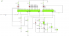
Update on my project. Did a logic simulation in yenka. Very limited program but somewhat useful. Would never do a final simulation in it but its very easy to use and if you just want to see if the logical side of the circuit works its a good for that in my opinion. So enough about the program and onto my findings. I made two separate diagrams as it got a little messy for my liking so one has the overall circuit but without the switch over of the first digit of the hour. The second being a demonstration of how the switch over would work. In the diagrams i made for the switch over its not a true tell of what the final circuit will look like as the transistors will be used as a switch for the power to each of the 4017 switched that alternate for the first digit of the hour. But other than that I was happy with my results. The idea i had works perfectly and this is what I will base my final design on. Pictures are included and if you have yenka i have included the diagram files as well, the program is free so if you don't have it its a quick download, Google will direct you to the page with a quick search. Keep in mind though when looking at these i am not going to use a 555 as the clock timer its just for this circuit as it was the simplest timer i could think of
On the works pc I can view the schematic png's, but not the tar file.
Yes I can make sort of sense of that, as much as a Sunday will allow anyway.
The only changes I'd make are the clock, a 4060 and 32.768 xtal would give good time, and on the second schematic, maybe it just because its as you say a representation but you have the 2nd and 3rd 4017's reset inputs floating when not reset, you'd need a pull down resistor to keep them stable.
'pull downs' with 4000 series will work, pull ups tend to be a prefered way esp with ttl or hc.
My nixie clocks use 4017's, in a different manner, 4 or 6 tubes and 1 4017, a pic clocks the 4017 to the correct output then turns on the correct tube, and so on as a multiplex, I can drive 60 neon segments with 8 o/p pins on the micro, no extra logic, you could do it with 3 pins using 2 4017's.
Ya the second diagram is not at all what i would have liked but its the best i could do to represent a working circuit. The transistors are not supposed to be connected to reset at all. It was just a way for me to test if the basic idea would work which it does. My idea was to have those transistors, powered depending on the state of the first 4017(one with 2 LED's), to be switches for the power of the 2nd and 3rd 4017s. The program i was using didn't show the power pins for the 4017 though so i had to improvise a little to get what i wanted. Should work though but there is a lot i still have to do and this is a long way from being finished. Got exams in a week and a bit and during this I'll be drawing up a final diagram but don't have a final time i could give anyone right now. But i'll keep on updating this thread as I go along.
Switching power to the 4017's allthough a lilttle unorthodox is one wa of doing it, if you do that then the 4017 might power up on a random value so you'd need a cap/resistor on the reset line to guarrantee power up on 0.
just received some pretty bad news for this project of mine, some news i feel dr pepper might know about. The only place these nixie tubes are supposedly made are russia and china, these places are both very very far away from me so its gonna be a very difficult for me to get my hands on them. So this means i will not be able to finish this project anytime soon. Alas i am not going to give up i will be constantly on the lookout and if you know of a supplier in south africa send them my way. Also i am still going to build the guts of this circuit so when the good stuff comes along (nixie tubes) it will be a few quick alterations to integrate them into the circuit. So I will finalize a design soon with the 4017 and instead of nixie tubes i'll use Led's to correspond to each pin of the nixie tube.
shipping to south africa is a nightmare. Heard plenty of horror stories from friends ordering from overseas and then because of the combination of a few bad factors items go missing and because of this a lot of companies wont insure the item once it gets into the country its their loss. So basicaly its insured until it gets into the country after that its a lucky draw. You can pay extra to get it insured in the country but then you pay more than the item is actually worth so its not worth it really to import small items like this. Shipping without insurance will cost a lot and im not going to insure it as that costs double to shipping cost. Unfortunately I'm not going for a expensive chance at getting them. I'm going to source all products that used them and disassemble them to get the nixie tubes but even this might be difficult but thanks for the idea will look into shipping it a little more.
Go ahead and start building, just use LED displays and make the appropriate hardware hooks to change the design.
Use a Priority encoder to get back to BCD, so you can drive an LED display.
Just make the "coolness factor" wait a bit longer.
You can 'make' a very basic nixie simulator using 10 leds, and you could power if from the nixie inverter ht output.
Actually it would look more like a dekatron but would work exactly as a nixie.
been slow going of late, Exams have really been tough and only one week in but the hardest are over now but still wont be able to get building till exams are all over. Enough about my life the project, i just want to swing an idea past everyone interested in helping and by the way i want to say thank you to everyone that has contributed to this thread has helped me come up with a solid idea i think will work and building will commence as soon as exams are done. So my idea for the 1hz precision timer was to use a quartz crystal with some circuit wizardry i found, take a look at the two, they're almost identical but want to get some opinions before i buy the parts, next weekend hopefully. http://www.hackersbench.com/Projects/1Hz/ &
**broken link removed**
hi,
The second type using a 4013 is the one I prefer, also make one the timing capacitors adjustable.
Use a 5pF to 50pF trimmer cap to set the precise 1Hz frequency.
E
ericgibbs
that is perfect exactly what i will do, little embarrassed to say this is the first time i have hear of a variable capacitor, 2 years of studying engineering and you'd think I'd of heard if it before, glad i know what it is now haha.
Also had an idea for the LED's is there a counter like the 4017 but instead of counting up the way it does it keeps the previous outputs "on" while counting up, so the number of LED's will be a reflection of what no. is being displayed. Don't think i will be able to get my hands on the nixie tubes so why not make it look cool with LED's
I agree with that, the resistor values are a little high on the first one.
Last time I used a 4060 I used a 470k across the xtal rather than a 10m, I think the breadboard capacitance was messing me up.
If you cant get a trimmer cap use a varicap diode and a trimpot.
found a place i can get them for a very good price if i cant get them from where i am planning to get them. Will only know by next weekend though. Found a 40pf to 6p8f trimmer cap for the equivalent of 0.16$ so that shouldn't be a problem. so your saying just replace either one of the 18pf caps with a trimmer cap and i will be able to get the frequency just right, very interested to see how much the frequency varies in practice.
Are you saying 6.8 to 40pf?, if you mean 40pf to 68 thats a little high, 32kc xtals I've used tend to like 15pf per side, you could connect a smaller cap in series with a larger trimmer to reduce it if req.
The 'pull' of an xtal depends on the xtal itself, watch xtals are fairly stable so you'll probably get around 100 to 200hz either way.
I have a pendulum clock made from a hard drive read head here on my desk, it has fixed 15pf caps either side of a 32kc xtal connected to timer 1 ext osc on a pic16f88, it keeps time to within a second or so a week.
6.8pf to 40pf. 1 second a week you say. I'd be happy with that. I'm gonna get the trimmer cap and play around a bit still but i feel i may end up going with the constant cap value if its only out by a second a week. Losing around about a minute a year isn't that bad and i can adjust it every now and then if it goes out of sync by to much
This site uses cookies to help personalise content, tailor your experience and to keep you logged in if you register.
By continuing to use this site, you are consenting to our use of cookies.