Continue to Site

Welcome to our site!

Electro Tech is an online community (with over 170,000 members) who enjoy talking about and building electronic circuits, projects and gadgets. To participate you need to register. Registration is free. Click here to register now.

  • Welcome to our site! Electro Tech is an online community (with over 170,000 members) who enjoy talking about and building electronic circuits, projects and gadgets. To participate you need to register. Registration is free. Click here to register now.

Nixie tube clock idea

Status
Not open for further replies.
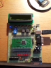
So I feel like i need to build one just because i think it is cool. Now that you've heard my awesome and very much backed idea here's my plan. I have a development board that i know i can program to count up. My idea however is not to use it as the brains but instead use a layered approach and hook up a few IC in series that will do the digit by digit counting of each part of the clock, ie one IC for the second digit in seconds, another for the first digit in seconds, 1 IC for the first digit of minutes ..... and so on. The dev board will be just to count and keep the seconds in time. I know this is a very simple and waste of processing power for a dev board but i dont want to integrate the dev board into the circuit to much. Hopefully i will be able to afford and think of something else that can do this in the future, right now though i would like to use the dev board as i would like to do a little pointless fun programming in this mini project. Now you may ask why I'm doing this and being a bit of a noob about it. I am a 2nd year electrical student and well i feel like. Something that's not to hard to build but somewhat usefull. All i need is a IC that can count up to a certain set number ranging from 0 to 9 so the whole range of the 10 base counting system at least. I've just been brainstorming ideas and this is the one i like the most but my only problem is i dont know of a IC that can do the kind of counting i'm looking for. I haven't got a basic concept design yet but i will put one up shortly, maybe by the end of the day or tomorrow atleast.

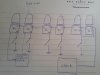
ah yes almost forgot to add the IC must have atleast 10 outputs for the pins of the nixie tube
 
Last edited:
What is the "development board"?
 
its a custom board, required and sold, by the course i'm studying, in parts to be built by each student. Uses a GT16 microprocessor. Very limited to what one can do with it as its just meant to be a beginners board, very beginners, like for people who have never programmed or even messed with IC on a breadboard before, I have done both so was a really interesting course for me to see how a micro works and also not to difficult as the programming concepts and circuitry concepts weren't to hard to understand. Take a look at the picture. Screen is not broken just had some text on it that I'm not too keen to put on a public forum so i blanked it out. Know there might not be enough info to go on up in my original post but i had the idea going and wanted to put it down somewhere. Idea is growing fast but when i have a proper concept design tomorrow I'll post again. Just wanted to get the brain juices flowing so long.
 

Attachments

  • 2013-07-22 17.42.15.png
    2013-07-22 17.42.15.png
    3.8 MB · Views: 232
10 outputs for the pixie tube? One input for each digit, 0-9? Then you need a counter/decoder... like a CD4017B
 
Mike odom
Ah mike your awesome. I think that's exactly what I'm looking for. From what I could pick up from the data sheet. If i interpreted it correctly it increases the counter with each positive pulse from the clock input and the counter is a direct representation of the output that will drive current, the others will not. Hope I'm understanding it properly. Used this datasheet, please have a look to see if I'm looking at the right thing https://www.futurlec.com/4000Series/CD4017.shtml
 
Generally you need a presetable counter, so you can do the 0 to 5 thing. The 4017 could possibly reduce the parts count for 0 to 9.

You follow the presetable BCD counter with a BCD to decimal decoder.

12:59 to 1:00 requires some work especially if you want to implement leading zero blanking. 13 has to preset to 01 and if the first digit is 0 then blank the tube.

You may be able to CHEAT for the compares using data selectors.

So you need two 00 to 59 counters and one
01 02 ... 10 11 12 01 02 thingy with blanking if the first digit is zero.
 
Last edited:
What current/voltage does the nixie need? You'll need driver stages between the IC and the nixie inputs.

Mike
Pixie tube? What are you on? :D
 
KeepItSimpleStupid
have though of that switch over from 12 to 1. Was thinking of using some kind of 2 stage circuit triggered by the 2nd digit in the hour. Might be complex but there's always a way. I feel kinda bad saying it might be complex since your screen name is keepitsimplestupid haha.
alec_t
I'm not 100% sure on this but i know you are right, I've read that they run on between 160 - 200 V so i will have to use a dual supply, 9V for my circuit and around 170V for my Nixie tubes. Just need to get my hand on some Nixie tubes before i can start messing around with them. Oh question about this 30 year old tech that hopefully someone knows, can a nixie tube run off AC or will i have to rectify my input for that too
 
Ok so here is a basic concept attached below. I have been thinking about the carry overs and this might be a crude method i have in mind. Before you read please look at the concept, I think it will help understand what I'm trying to do. So with digit displays that need only go up to 5 like seconds and minutes i was thinking of still using the CD4017 but instead of using the carry bit just use the 7th output bit to simultaneously reset the counter itself and increment the next counter, so basically it will never overflow, the chip will always reset itself when it gets to a number to high. this can be used again for the first digit on the hour. Remember the 2 stages, haven't figured out this part yet, stage 1 will count from 1 to 9, not 0 to 9 if you remember it goes 12:59 to 1:00 as keepitsimplestupid explained. This will just require different wiring which isn't a problem at all. and then again for the second stage which will count from 0 to 2. My 2 stage circuit i feel should be triggered by the 2nd digit in the hour. So if it is 0 then the first digit counts to 9 overflows and increments the second digit which will trigger the 2nd stage causing a switch over of some kind so the first digit now only counts to 2.For the switch over i had the idea of using a memory switch of which the output powers two CD4017's which count from 0 to 2 and 1 to 9 respectively, the output will be inverted for one of the CD4017 so only one CD4017 is on for the first digit at any given time. Also you will see the switches. quickly on that those are to set the time for each digit. each switch just increments the value displayed if pressed except for the seconds where both digits are reset to 0. One last note, I've decided to scrap that thought of using the dev board, Only wanted to use it cause it can be an accurate counter but it needs to be powered by USB so not very ideal, I was thinking off using a 555 as the clock and setting it up as an oscillator. My only worry is that it isn't accurate enough and i keep having to correct the clock.
ericgibbs
thank you man, also i have seen a lot of these on the internet but i really wanted to come up with a different way of doing it plus most of them use some kind of programmable IC and I don't want that at all, plus i want the circuit for the clock to be interchangeable so if i don't like the result i'm getting i can easily change it
 

Attachments

  • 2013-10-05 12.50.44.jpg
    2013-10-05 12.50.44.jpg
    3.9 MB · Views: 195
There are plenty of Nixie tube PS circuits and supplies on the web.

You will always do better with line frequency time-keeping in the long run.

The OP said:
0 to 2 and 1 to 9 respectively

What?

You would miss 1:00 2:00 3:00 .....12:00; if you only counted from 1-9 on the first stage.

Just a little modular approach: 00 to 59 and 00 to 59 and the odd counter.

I do suggest that you learn a simulator such as LTSPICE which is free.
 
KeepItSimpleStupid
it shouldn't miss the 10 11 and 12. It would count from 1 to 9 then 0 to 2. this is only for the first digit in the hours, its the only one that would need a setup like this. So i would get the whole range, think of each digit individually. Say on the display is showed; 12:59:59. If there was one more cycle on the clock that sent a signal to the first digit in seconds then the first digit in seconds would overflow sending a signal to the second digit, so the first now becomes 0, and since the second digit is 5 and it is incremented it will reset itself to 0 and send a signal to the first digit in the minutes to increments, since the first digit in minutes is 9 it will overflow and send a signal to the second digit in minutes and reset to 0, since the second digit is 5 it will reset itself and send an signal to the first digit in hours so it too will be 0. Now since the first digit in hours is in its "second stage" since there is a 1 on the second digit of hours, it will reset itself and send a signal to hours, since hours is on 1 it will reset itself and send a signal to switch back to "stage 1" for the first digit of the hours. Since hours counts from 1 to 9 it will display 1 first so at the end of this sequence you will have; 1:00:00 so it will not miss out any numbers. I do know how to use LTSpice but not very well to be honest, haven't tried simulating it yet. I do understand the whole staged part for the first digit in hours is confusing still piecing the idea together on that one. Gonna simulate it and fix it as i go
 
I was thinking off using a 555 as the clock
Not accurate enough.
i want the circuit for the clock to be interchangeable so if i don't like the result i'm getting i can easily change it
If you make it with discrete logic (instead of a micro), it won't be easily changeable.
 
The approach I was thinking about was:

If 00 preset to 01
and if 13 preset to 01; could mean... If 12, then next input will preset to 01.

But pay attention to timing.

I'll be working with this, **broken link removed** in the near future. It uses a CD4510. I need a presetable down counter. 6 to 1 or 6 to zero. I don't really care. 6 to 1 would be ideal.
 
The Nixie tubes need at least 100 Volts or more to strike properly 170 Volts DC is ideal.
The current needs to be limited to 1mA or less, depending upon what type of Nixie is used.

Old driver IC's were the TTL 74141 IC's which are very hard to get although ebay sells the Russian version ( K155 ID1 )of it.
In case you use the 4017 IC you need a high voltsge transistor ( MPSA42 ) to do the Nixie switching as a 4017 will blow up without an external driver.
 
haha KeepItSimpleStupid that's amazing, i doubt i would have the patience to build that. Would be a lot of fun and probably very rewarding wow. Love the idea.

RODALCO your thinking on the same line as me with the high voltage transistors. Read about the TTL chips but i doubt I'd be able to get any and I'm not looking to spend to much on this besides the nixie tubes and the PSU. I will just limit the current going through the nixie tube with a resistor, gonna make it simple and easy to control but will have to see.

gonna post findings of simulations next weekend. been real busy with studies this weekend, just been spending breaks working on this really so haven't had a big enough break to do a full simulation yet.
 
I've made a few.
There are as mentioned lots of ideas and schems.
My favorite power supply for them is the lowly 555, some say its naff but it works on the 4 or 5 clocks I have.
 
That Nixie clock without IC's is simply amazing.
Thanks for posting that photo.
 
Status
Not open for further replies.

Latest threads

New Articles From Microcontroller Tips

Back
Top