Continue to Site

Welcome to our site!

Electro Tech is an online community (with over 170,000 members) who enjoy talking about and building electronic circuits, projects and gadgets. To participate you need to register. Registration is free. Click here to register now.

  • Welcome to our site! Electro Tech is an online community (with over 170,000 members) who enjoy talking about and building electronic circuits, projects and gadgets. To participate you need to register. Registration is free. Click here to register now.

NiCad Battery bank Balance circuit (1.2v 32Ah x 20 cells)

Status
Not open for further replies.

TJP

New Member
Hi Guys - your help here is highly appreciated !

I have 20 x NiCad (flooded cells) of 1,2v 32Ah each, wired in series into a 24v bank. Float voltages per cell is 1.40 - 1.42 V/cell.

(I actually have 80 cells connected in 4 x 20 cells each iaw for a total of 128 Ah - charged with a 24v 3KWh Invertor )


Have looked at off the shelf BMS's but is above my pay grade - (most are designed for other batteries types and I really only need balancing)

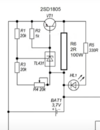
I had a look at the attached circuit found it on YT. Can this circuit be modified to balance 1.4v cells even if I need to build 1 each for every cell.

I am aware that the cell voltage of 1.4v is low for most components to function on - which means that 24v from the bank will be needed to power the circuit

1. will need to use the bank voltages of 24 vdc via n ± LM7805 or something similar circuit to drive the BMS's for each of the cells.

2. Then a censing circuit to read the cell voltage 1.40 v adjustable (preferably multiturn pot) and use this to activate the BMS in 1. to balance each cell via a load resistor.

3. I think both circuits need to be isolated from each other by an OPTO or something.

Any ideas please share - A simple but effective circuit that I can build to balance each cell would be appreciated.

My electronics knowledge is quite limited component wise - I can build and test n circuit thanks to YT and other platforms that I have learned from ect.. But the intricacy's of component values etc. not well versed.

Thank you for your interest and help in this project

TP
 

Attachments

  • TL431.PNG
    TL431.PNG
    95.5 KB · Views: 366
Battery Balancer
I can't find it now but I saw your circuit from china for very little money. Adjustable over a voltage range. Search alibaba.com or amazon for battery balancer.

Your circuit has a TL431 inside. It can not work below 2.5V or maybe 3V. There are other versions of the part that should work to 1.25V. If you need the circuit modified one of us could take a look at it more.
Ron Simpson
ps. The battery Balancers I saw on line will not work below 3V so watch out.
 
  • Like
Reactions: TJP
Battery Balancer
I can't find it now but I saw your circuit from china for very little money. Adjustable over a voltage range. Search alibaba.com or amazon for battery balancer.

Your circuit has a TL431 inside. It can not work below 2.5V or maybe 3V. There are other versions of the part that should work to 1.25V. If you need the circuit modified one of us could take a look at it more.
Ron Simpson
ps. The battery Balancers I saw on line will not work below 3V so watch out.
Hi Ron

I noticed that most BMS dont work that low a voltage, I would really appreciate if it can be looked at. If one can power the main circuit from the 24v supply side and the sensor side from the 1.4v from the cel tie self can this be n workable !

What version of the TL431 can go that low? or is there maybe a nother work arround ?

Ron thanks for looking in on a Saturday night evening much appreciated.

TP

that balancer looks nice but min voltage is 1.8v
 
your circuit. The TL432 looks at the spot where I wrote 2.5V. If the voltage is less than 2.5V it pulls very little power and the transistor is off. If the voltage is more than 2.5V it pulls power turning on the transistor and putting power into R6 and the LED. R1, R3&R4 divide down the battery voltage.

There are several voltage references much like the TL431 but with a lower input level. TL4051 is an example set at 1.224V.

I need to think about this a little. The TL4051 acts strange when the battery gets below 1.6V.
1636223613915.png
 
NiCd cells, including wet types, are self-balancing - just trickle charge them at 1/20C or less and they will charge fine & not be harmed.

As long as they are then allowed a low level trickle charge for some time after each discharge and normal charge cycle, they will stay balanced.

The charge voltage should be 1.55V per cell, set for the overall battery. Once that voltage is reached at full current charging, reduce to 1/10C then when it's reached again reduce to a low trickle charge, 1/20C max, down to 1/50C even.
 
Last edited:
There are a number of voltage Comparators with built in voltage reference. Do not use the LT6703 or most, because then do not work below 1.4V. Use the MAX9064 because it works at 0.8V to 5.5V. Internally there is a 0.2V ref voltage. When the "+" input gets above 0.2V, Q1 & Q2 turn on and dump power into R4. I need to know what the charging current is to design the rest of the circuit. I did not put a LED in the circuit because there is no LED that I can find that will light near 1.4V. (IR LED work but I can not see them, lol)
1636231234101.png

Good luck Ron Simpson
ps
If you move to 1.55V maybe we can get a LED to light.
 
NiCd cells, including wet types, are self-balancing - just trickle charge them at 1/20C or less and they will charge fine & not be harmed.

As long as they are then allowed a low level trickle charge for some time after each discharge and normal charge cycle, they will stay balanced.

The charge voltage should be 1.55V per cell, set for the overall battery. Once that voltage is reached at full current charging, reduce to 1/10C then when it's reached again reduce to a low trickle charge, 1/20C max, down to 1/50C even.

Gees you guys are quick - appreciate ! much much appreciate ! !

@rjenkinsgb

Thank you - I don't know much about NiCad's had these for n while and never used them. Currently in SA we have serious problems with load shedding jumping between stages 2 and 4 see attached. Need to keep the PC and the lights going for now. The idea is to get to Solar ASAP but funds is limited will need to do that in stages. At this stage using mains to charge the pack ready for the next load shedding stage. Currant load is about ±155VA.

I don't know how much time would be needed to trickle charge the battery pack to get them balanced and whether these load shedding stages are to close to achieve that ?

The invertor I have is a 3Kw - 3 stage charger.
*BULK* (constant currant) *ABSORPTION* (constant voltage) *MAINTANACE* (floating) - in each charge cycle.

MAX mains charging currant is 30A, BULK max voltage can be set to 29.2v, MAINTANACE (floating) max voltage can be set to 29.2v.

Would appreciate is you can give me some pointers as to settings to be used to best charge this battery pack.


There are a number of voltage Comparators with built in voltage reference. Do not use the LT6703 or most, because then do not work below 1.4V. Use the MAX9064 because it works at 0.8V to 5.5V. Internally there is a 0.2V ref voltage. When the "+" input gets above 0.2V, Q1 & Q2 turn on and dump power into R4. I need to know what the charging current is to design the rest of the circuit. I did not put a LED in the circuit because there is no LED that I can find that will light near 1.4V. (IR LED work but I can not see them, lol)
View attachment 134368
Good luck Ron Simpson
ps
If you move to 1.55V maybe we can get a LED to light.

ronsimpson

Thanks once again for your help (all of you)

currently the battery pack is charged at 30A at 29 v - thus each of the 4 rows of 20 cells is getting 7.5A
float charge is set at 1.42v per cell iaw 28.4 v for the battery pack overall.

Hope this help - please ask for more information if required ! I would not want to hurt these cells as at this time they are really helping us a lot !

PS: getting an LED to indicate would be of tremendous help - instead of measuring the voltage of each cell every time. ;)

THANK YOU A LOT YOU GUYS ARE AWSOME ! ! !

TP
 

Attachments

  • WhatsApp Image 2021-11-07 at 12.38.48.jpeg
    WhatsApp Image 2021-11-07 at 12.38.48.jpeg
    41.2 KB · Views: 239
MAX mains charging currant is 30A, BULK max voltage can be set to 29.2v, MAINTANACE (floating) max voltage can be set to 29.2v.

Would appreciate is you can give me some pointers as to settings to be used to best charge this battery pack.
20 x 1.55V = 31V
At 29V, you will never achieve full capacity on a 20 cell pack.

I'd guess that charger is intended for lead-acid batteries, as the voltages would fit that application well.
 
Just thinking.
There are 4 strings of batteries which receive 30A total. So each string sees 7.5A.
If one string has a open cell then no current will flow in that string. If one string is charged and one is not then the current will flow in (maybe) one string. Question: How much of the 30A could be going through one string? Maybe 15A??

Next question: To make it simple think 7.5A charger and one string of batteries. How much current does the balancer need to handle?
1) If all the cells are new and good and of the same age, then they should all charge as one. But of one cell is not like the others then we probably need to balance at full 7.5A.

2) We have been talking about a circuit that measures 1.4V and turns on (or off) a 7.5A bypass resistor. BUT If the balances was "smart" it would compart all the voltages in a string and bypass current even at a low voltage. Say the voltage average was 1.2V/cell but one battery was running at 1.25V then that cell could be bypassed (1A or 2A) to keep it aligned with its brothers. In this case very likely 2A will keep the charge balanced.

3) When all the batteries are charged what do we do? Bypass all the current to ground? Stop the charger? Stop the balancing?

I can build circuits but I do not have enough experience to know how batteries should be balanced in a "parallel/series" system. I built a 12/24V 50A two battery balancer for automotive. It did not waste power in resistors like the small balancers do. My two battery engineer friends are no longer with us.
 
20 x 1.55V = 31V
At 29V, you will never achieve full capacity on a 20 cell pack.

I'd guess that charger is intended for lead-acid batteries, as the voltages would fit that application well.
I guess so its the price to pay while learning. What will the outcome of this be ?

Can I add a separate charger to raise the voltage to 31 v on the charging cycle?

TP
 
Just thinking.
There are 4 strings of batteries which receive 30A total. So each string sees 7.5A.
If one string has a open cell then no current will flow in that string. If one string is charged and one is not then the current will flow in (maybe) one string. Question: How much of the 30A could be going through one string? Maybe 15A??

Next question: To make it simple think 7.5A charger and one string of batteries. How much current does the balancer need to handle?
1) If all the cells are new and good and of the same age, then they should all charge as one. But of one cell is not like the others then we probably need to balance at full 7.5A.

2) We have been talking about a circuit that measures 1.4V and turns on (or off) a 7.5A bypass resistor. BUT If the balances was "smart" it would compart all the voltages in a string and bypass current even at a low voltage. Say the voltage average was 1.2V/cell but one battery was running at 1.25V then that cell could be bypassed (1A or 2A) to keep it aligned with its brothers. In this case very likely 2A will keep the charge balanced.

3) When all the batteries are charged what do we do? Bypass all the current to ground? Stop the charger? Stop the balancing?

I can build circuits but I do not have enough experience to know how batteries should be balanced in a "parallel/series" system. I built a 12/24V 50A two battery balancer for automotive. It did not waste power in resistors like the small balancers do. My two battery engineer friends are no longer with us.

thanx Ron

A conundrum of questions some that I have asked myself.

Its just that the off shelf units are out of my reach at this stage. At this stage some of the cells are running at 1.51 and some as low as 1.35v. Hopefully they wont get damaged but as rjenkinsgb said the pack will never reach full potential.

Maybe I Just from time to time disconnect the invertor - charge the pack with a separate charger to 31v get it to self balance this way as rjenkinsgb suggested ?

The specs for these cells says that 1.5v is the equalizing voltage - how often can this be done ?

I really appreciate your time and feedback thus far - maybe I need to reach more - I believe there could be an answer to this.

I found this info some time ago not sure how feasible it could be - if some one can give any info on this please. see attached.

thank you

TP
 

Attachments

  • Diodes to balance.PNG
    Diodes to balance.PNG
    141.9 KB · Views: 216
I found this info some time ago not sure how feasible it could be - if some one can give any info on this please. see attached.
The first part has the voltage too low for the cells.

Just read the very last line on the item you linked to.. Balancing arrangements are not needed with NiCD or NiMH; it is with lithium type cells as they cannot stand any over-charge, unlike nickel and lead types.

You could charge each bank (32AH) at eg. 1.5A (approx. C/20) for days if you wished. The cells should be fully charged and balanced after a day or so.

You would need a higher voltage PSU and a current limiter such as a light bulb that would take an amp or two at the voltage difference between the battery and the PSU.
Thanks for the feedback.

I have a PSU that is adjustable 14v -19v at 5 amp. Can set it to 15.5 v ?

Can I charge and balance 10 cells at a time the way described. and put them back each 32a row at a time ?

As I understand the lamp/load is to get the amps down to 1.5 amps?

Am i right in this thinking

Thanks TP
 
The first part has the voltage too low for the cells.

Just read the very last line on the item you linked to.. Balancing arrangements are not needed with NiCD or NiMH; it is with lithium type cells as they cannot stand any over-charge, unlike nickel and lead types.

You could charge each bank (32AH) at eg. 1.5A (approx. C/20) for days if you wished. The cells should be fully charged and balanced after a day or so.

You would need a higher voltage PSU and a current limiter such as a light bulb that would take an amp or two at the voltage difference between the battery and the PSU.

Can I parallel 10 cells x 2 rows and get the same results ? Doing it as I have explained above ?
 
I have a PSU that is adjustable 14v -19v at 5 amp. Can set it to 15.5 v ?

Can I charge and balance 10 cells at a time the way described. and put them back each 32a row at a time ?

As I understand the lamp/load is to get the amps down to 1.5 amps?

Am i right in this thinking
Yes, pretty much so.

The difference is that the PSU needs to be set to a higher voltage, to allow for the lamp or resistor voltage.

Something like a car headlamp bulb should work, they are very low resistance when cold and if you have an ammeter in series you should be able to adjust the PSU output to get around C/20 rate, eg. a current 1/20th of the amp-hour rating or around one and a half amps for each single string of 32AH cells.

You could do two or three strings at the same time, but use a separate lamp in series with each - do not directly connect sets of cells in parallel, as if there is even a slight difference in voltage the current could be enormous.

Once all cells are fully charged and have been on the low current trickle for a day or two as above, if you wish to parallel batteries you can connect the negatives and use the headlamp bulbs to cross-connect the positives until the all the battery voltages are exactly equal, then direct-connect them.

Cells are balancing 2 rows of 10 cells each.

each row connected via lamp to Ameter and PSU.

PSU set to 16.45 volts to get a 1.5 amp avg for each row. about a 200 ma difference between the rows.

do I need to adjust the voltage higher as the amps drop or not

Thanks

TP
 
Status
Not open for further replies.

Latest threads

New Articles From Microcontroller Tips

Back
Top